Sunday, August 31, 2014

PWM controller with 555 timer chip

PWM
IC Timer 555 has a basic PWM controller with pulse width control feature 0 .. 100% which is controlled using the R1, at the time of controlling the oscillator frequency relatively stabi so it may be used to build the Simple PWM controller.

Frequency of Simple PWM controller 555 depending on the value of R1 and C1, values ​​shown R1 and C1 will form the output with a frequency of 170 to 200 Hz. Diode-diode used in the Simple PWM controller With this 555 can use a 1N4148.

R2, R3 and C3 form a giver triger circuit beginning at the reset IC 555 for 2 seconds. If you want to use a series of Simple PWM controller 555 with the V + not +12 V, it does not matter to raise tilapia R2 where (V + * R2) / (R2 + R3) is about 2, because it limits the signal level reset is 0.5 .. 1V. If you do not do that, then signal the kickstart to get too close to the limit reset signal reception.

PWM
PWM controller circuit

Q output of 555 on the Simple PWM controller circuit 555 is used for driver PWM pulse, so that the discharge pin is used for transistor output driver instead. This is an open collector output, and is used as an active signal is low, so it can work. D3 protects the output transistor of the load induction. You may replace any suitable transistors for Q1, BD140 is 1.5 amps.

C4 and C5 is the power decoupling capacitor for the IC 555 on the Simple PWM controller circuit 555, which produce relatively large level of push-pull output stage.
Read More..

Simple Programmable Bandpass using twin t bridge

The Simple Programmable Bandpass using twin-t bridge schema gives a programmable bandpass where both the cut-over frequency and the gain, A, are controlled independently. In the twin-T bridge the resistors R and R/2 are replaced by two double FETs, 430, the channel resistance of the first one in the series, the channel resistances of the second one are in parallel as to stimulate the resistance R/2. Both these resistors are controlled by Vc which ranges from 0 V to about 1 V. The gain of the schema is set by means of the resistors R2 and R3. 

Simple Programmable Bandpass using twin-t bridge Circuit Diagram

Simple
Read More..

Altium Designer 10 0 – Free Download

A unified electronic product development solution Altium Designer is the world’s first and only unified electronic product development system that allows engineers to take a design from concept to completion within a single application.


Don’t limit your design horizons. Get yourself out of the traditional design box and into holistic design. Use all the available technologies and devices to bring your ideas to life and turn them into the smart, connected products that we’ll all be using tomorrow.

Altium

Altium Designer 10.0

That’s what Altium Designer is all about – freeing you from the constraints of traditional design limitations and the old “divide and conquer” approach. Altium Designer provides one single unified solution for the entire design process. It allows you to explore and do more, do it in new ways, and design things that haven’t even been thought of yet. Think and design beyond the confines of the device itself and start designing your customer’s total product experience.

That’s next-generation electronics design. That’s Altium Designer.

The entire product development process with a single unified design solution A single solution to develop hardware, programmable hardware and software Take designs from concept to manufacture within a single unified environment A single model of the design data, and a single design data storage system

Freely explore design concepts ‘on-the-fly’ Explore devices from different vendors with minimal design reengineering Easily explore design concepts and options before committing to final hardware Use IP from any source, without being restricted to vendor-specific ‘sticky IP’

Rapidly prototype using a live, interactive hardware development system Develop, explore and debug designs on real hardware, in real-time with ‘LiveDesign’ Harness the full potential of reprogrammable devices with soft-centric design Change software and hardware with equal ease and on-the-fly

Smooth the path from design to board layout and manufacture Single centralized data source simplifies version control and component management Visualize and interact with board designs in real-time 3D, within the PCB editor Seamless collaboration with MCAD designers and other engineering teams

Easily connect to wider company systems Single access point for all design data simplifies links for data management systems Plug-in capability and built-in interfaces for external data management All involved in product development process access one design environment

Be equipped for the future with the latest design technologies Expand existing skill sets while harnessing the latest devices and techniques Make soft design and the creation of device intelligence the focus of design Immediately access new technology through consistent and frequent updates

Be productive right ‘out-of-the-box’ All tools and technologies in the box, including parts libraries and royalty-fee IP No need to purchase costly add-ons to make a complete solution Continually updated with latest devices and technologies

See Whats new in release 10

more info @http://www.altium.com/Products/AltiumDesigner/

Download
Part 1
Part 2
Part 3
Read More..

Simple Diode Feedback Comparator Wiring diagram Schematic

This is a Simple Diode Feedback Comparator Circuit Diagram. This schema can drive an LED display with constant current independently of wide power supply voltage changes. It can operate with a power supply range of at least 4V to 30V. With 10M resistances for R2 and R3 and the inverting input of the comparator grounded, the schema becomes an LED driver with very high input impedance. The schema can also be used in many other applications where a controllable constant current source is needed.

Diode Feedback Comparator Circuit Diagram

Diode

Read More..

Saturday, August 30, 2014

Introduction to Amplifier Rise

Amplification is the method of increasing the amplitude of a AC signal current or voltage such as audio signal for sound or video signal for a television picture. The amplifier allows a small input signal to control a bigger amount of power in the output schema. The output signal is a replica of the original input signal but has higher amplitude.

Amplification is necessary as in most applications, the signal is weak to be used directly. For example, an audio output of 1mV from a microphone is unable to drive a loud speaker which requires a few volts to operate. Hence, the signal require to be amplified to a few volts before it can be fed in to the loud speaker.

NP N Transistor Circuit Configurations
An example of different type of transistor configurations in the schema is as shown in Figure one below.


(1) The common emitter(CE) schema makes use of emitter as its common electrode. The input signal is applied to the base and the amplified output is taken from the collector. This is the usually use because its the best combination of current gain & voltage gain.

(2) The common base (CB) schema makes use of base as its common electrode. The input signal is applied to the emitter & the amplified output is taken from the collector. The comparatively high emitter current compared to the base current ends in low input impedance value. For this reason, the CB schema is never used.

(3) The common collector (CC) schema makes use of collector as its common electrode. The input signal is applied to the base & the amplified output is taken from the emitter. This schema is also called an emitter follower. This name means that the output signal voltage at the emitter follows the input signal at the base with the same phase but less amplitude. The voltage gain is less than one & is usually used for impedance matching. Its high input at the base as a load for the earlier schema & low output impedance at the emitter as a signal source for the next schema.

Classes

They can be classified in to classes A, B, C & AB. They are defined based on the percent of the cycle of input signal that can produce output current.

In Class A, the output current flows for the full cycle of 360 degree of input signal. The distortion is the lowest with around 5% to 10% &an efficiency of 20% to 40%. In general, most tiny signal operate class A

In Class C, the output current flows for less than half of the input cycle. Typical operation is 120 degree of input current in the coursework of the positive half cycle of the input current. This class has an efficiency of 80% but has the highest distortion. This class is usually used for RF amplification with a tuned schema in the output.

In Class B, the output current flows for half of the input cycle which is around 180 degree. Class B operation lies between class A & class C. Classes B are usually connected in pairs & in such a schema called push-pull amplifier. The push pull is often used for audio power output to a loud speaker.

In Class AB, it offers a compromise between the low distortion of class A & the higher power of class B. It is usually used for push pull audio power amplifiers.
Read More..

Long range Burglar Alarm Using Laser Torch

Laser torch-based burglar alarms normally work in darkness only. But this long-range photoelectric alarm can work reliably in daytime also to warn you against intruders in your big compounds, etc. The alarm comprises laser transmitter and receiver units, which are to be mounted on the opposite pillars of the entry gate. Whenever anyone enters to interrupt the transmitted laser beam falling on the receiver, the buzzer in the receiver schema sounds an alarm.

The range of this burglar alarm is around 30 metres, which means you can place the transmitter and the receiver up to 30 metres apart. Since the laser torch can transmit light up to a distance of 500 metres, this range can be increased by orienting the phototransistor sensor properly. To avoid false triggering by sunlight, mount the phototransistor sensor such that it doesn’t directly face sunlight.

 Long-range Burglar Alarm Using Laser Torch

Long-range

The transmitter schema is powered by 3V DC. The astable multivibrator built around timer 7555 (IC1) produces 5.25kHz frequency. CMOS version of timer 7555 is used for low-voltage operation. The body of the laser torch is connected to the emitter of npn transistor T1 and the spring-loaded lead protruding from inside the torch is connected to the ground.

The receiver schema is powered by 12V DC. It uses photoDarlington 2N5777 (T2) to sense the laser beam transmitted from the laser torch. The output beam signals from photoDarlington are given to the two-stage amplifier followed by switching schema, etc. As long as the laser beam falls on photoDarlington T2, relay RL1 remains un-energised and the buzzer does not sound. Also, LED1 doesn’t glow.


www.streampowers.blogspot.com

Fig. 2: Receiver schema

When anyone interrupts the laser beam falling on photoDarlington T2, npn transistor T6 stops conducting and npn transistor T7 is driven into conduction. As a result, LED1 glows and relay RL1 energises to sound the buzzer for a few seconds (determined by the values of resistor R15 and capacitor C10). At the same time, the large indication load (230V AC alarm for louder sounds or any other device for momentary indication) also gets activated as it is connected to 230V AC mains via normally opened (N/O) contact of relay RL1.


Sourced By: EFY Author ;  Pradeep G.
Read More..

Save Your Ears A Noise Meter

‘Hello… HELLO! Are you deaf? Do you have disco ears?’ If people ask you this and you’re still well below 80 , you may be suffering from hearing loss, which can come from (prolonged) listening to very loud music. You won’t notice how bad it is until it’s too late, and after that you won’t be able to hear your favorite music the way it really is – so an expensive sound system is no longer a sound investment. To avoid all this, use the i-trixx sound meter to save your ears (and your neighbors ears!).
With just a handful of components, you can build a simple but effective sound level meter for your sound system. This sort of schema is also called a VU meter. The abbreviation ‘VU’ stands for ‘volume unit’, which is used to express the average value of a music signal over a short time. The VU meter described here is what is called a ‘passive’ type. This means it does not need a separate power supply, since the power is provided by the input signal. This makes it easy to use: just connect it to the loudspeaker terminals (the polarity doesn’t matter) and you’re all set.
The more LEDs that light up while the music is playing, the more you should be asking yourself how well you are treating your ears (and your neighbours’ ears). Of course, this isn’t an accurately calibrated meter. The schema design is too simple (and too inexpensive) for that. However, you can have a non-disco type (or your neighbors) tell you when the music is really too loud, and the maximum number of LED lit up at that time can serve you as a good reference for the maximum tolerable sound level.
Although this is a passive VU meter, it contains active components in the form of two transistors and six FETs. Seven LEDs light up in steps to show how much power is being pumped into the loudspeaker. The steps correspond to the power levels shown in the schematic for a sine-wave signal into an 8-ohm load. LED D1 lights up fi rst at low loudspeaker voltages. As the music power increases, the following LEDs (D2, D3, and so on) light up as well. The LEDs thus dance to the rhythm of the music (especially the bass notes).
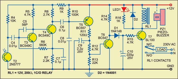
Circuit diagram:
noise Noise Meter Circuit Diagram
This schema can easily be assembled on a small piece of prototyping board. Use low-current types for the LEDs. They have a low forward voltage and are fairly bright at current levels as low as 1 mA. Connect the VU meter to the loudspeaker you want to monitor. If LED D2 never lights up (it remains dark even when LED D3 lights up), reverse the polarity of diode D8 (we have more to say about this later on). In addition, bear in mind that the sound from the speaker will have to be fairly loud before the LEDs will start lighting up.
If you want to know more about the technical details this VU meter, keep on reading. Each LED is driven by its own current source so it will not be overloaded with too much current when the input voltage increases. The current sources also ensure that the final amplifier is not loaded any more than necessary. The current sources for LEDs D1–D6 are formed by FET diagram. A FET can be made to supply a fixed current by simply connecting a resistor to the source lead (resistors R1–R6 in this case). With a resistance of 1 kΩ, the current is theoretically limited to 1 mA. However, in practice FETs have a especially broad tolerance range. The actual current level with our prototype ranged from 0.65 mA to 0.98 mA.
To ensure that each LED only lights up starting at a defined voltage, a Zener diode (D8–D13) is connected in series with each LED starting with D2. The Zener voltage must be approximately 3 V less than the voltage necessary for the indicated power level. The 3-V offset is a consequence of the voltage losses resulting from the LED, the FET, the rectifier, and the over voltage protection. The over voltage protection is combined with the current source for LED D7. One problem with using FETs as current sources is that the maximum rated drain–source voltage of the types used here is only 30 V.
If you want to use the schema with an especially powerful fi nal amplifier, a maximum input level of slightly more than 30 V is much too low. We thus decided to double the limit. This job is handled by T7 and T8. If the amplitude of the applied signal is less than 30 V, T8 buffers the rectified voltage on C1. This means that when only the first LED is lit, the additional voltage drop of the over voltage protection schema is primarily determined by the base–emitter voltage of T8. The maximum worst-case voltage drop across R8 is 0.7 V when all the LEDs are on, but it has increasingly less effect as the input voltage rises.
R8 is necessary so the base voltage can be regulated. R7 is fitted in series with LED D7 and Zener diode D13, and the voltage drop across R7 is used to cause transistor T7 to conduct. This voltage may be around 0.3 V at very low current levels, but with a current of a few mili-amperes it can be assumed to be 0.6 V. Transistor T7 starts conducting if the input voltage rises above the threshold voltage of D7 and D13, and this reduces the voltage on the base of T8. This negative feedback stabilizes the supply voltage for the LEDs at a level of around 30 V. With a value of 390 Ω for R7, the current through LED D7 will be slightly more than 1 mA.
This has been done intentionally so D7 will be a bit brighter than the other LEDs when the signal level is above 30 V. When the voltage is higher than 30 V, the schema draws additional current due to the voltage drop across R8. The AC voltage on the loudspeaker terminals is half-wave rectifi ed by diode D14. This standard diode can handle 1 A at 400 V. The peak current level can be considerably higher, but don’t forget that the current still has to be provided by the fi nal amplifier.
Resistor R9 is included in series with the input to keep the additional load on the fi nal amplifi er within safe bounds and limit the interference or distortion that may result from this load. The peak current can never exceed 1.5 A (the charging current of C1), even when the schema is connected directly to an AC voltage with an amplitude of 60 V. C1 also determines how long the LEDs stay lit. This brings us to an important aspect of the schema, which you may wish to experiment with in combination with the current through the LEDs.
An important consideration in the schema design is to keep the load on the fi nal amplifi er to a minimum. However, the combination of R9 and C1 causes an averaging of the complex music signal. The peak signal levels in the music are higher (or even much higher) than the average value. Tests made under actual conditions show that the applied peak power can easily be a factor of 2 to 4 greater than what is indicated by this VU meter. This amounts to 240 W or more with an 8-Ω loudspeaker.
You can reduce the value of C1 to make the schema respond more quickly (and thus more accurately) to peak signal levels. Now a few comments on D8. You may receive a stabistor (for example, from the Philips BZV86 series or the like) for D8. Unlike a Zener diode, a stabistor must be connected in the forward-biased direction. A stabistor actually consists of a set of PN junctions in series (or ordinary forward-biased diodes). Check this carefully: if D2 does not light up when D8 is fi tted as a normal Zener diode, then D8 quite likely a stabistor, so you should fi t it the other way round.
Read More..

Simple Audio Meter Wiring diagram Schematic

This is an audio meter, a kind of decibel simpler, used to measure the sound directly in the schema or a sound output device. It is very simple, using only two transistors BC107, potentiometer VR2 adjusts the input level and the level of VR1 VU. This meter audio should only be used for bench testing and should not be used for calibration.


Simple Audio Meter Circuit Diagram

Simple


Simple Audio Meter Circuit Diagram
Read More..

Alarm using your own Voice

This alarm plays your prerecorded voice message. It is built around the readily available quartz clock. Take the buzzer out of the quartz clock and connect its positive terminal to pin 1 and negative terminal to pin 2 of optocoupler IC MCT2E (IC2). Pin 4 of IC2 is grounded and pin 5 is connected to trigger pin 2 of monostable multivibrator IC 555 (IC3) as shown in Fig. 2.

Alarm

Fig. 1: Voice recording schema

Fig. 1 shows the schema for recording your voice message. When you press switch S2, it plays the meassage. The control schema shown in Fig. 2 avoids the need for pressing switch S2 and thereby sounding the voice alarm automatically at the preset time.

Connect points A and B of the recording schema to the corresponding points A and B of the control schema. After making the connections, press record switch S1 to record your 6-second voice message through condenser microphone. Set the desired alarm time in quartz clock. At the time of alarm, buzzer terminals provide voltage to the internal LED of optocoupler IC2. This results in conduction of internal transistor of IC2, and its collector voltage at pin 5 drops to trigger IC3. The output of IC3 goes high for approximately 6 seconds. During this period, the prerecorded message is heard continuously. The message repeats every 6 seconds. The sound is loud enough in a room.

Alarm

Fig. 2: Voice control schema

The schema operates off 3 volts and it can be easily fitted in a small box and fixed on the back side of the alarm quartz clock.


Sourced by: EFY Author:  Naga Babu Araya
Read More..

Friday, August 29, 2014

Power audio amplifier TDA1099SP

Power audio amplifier TDA1099SP circuit diagram

Read More..

Evolving Technology and Auto Sound Systems

Finding auto sound systems that can keep up with the constantly evolving technology of today is a real challenge for many car and sound enthusiasts not only around the nation but also around the world. There was a time in the not so distant past when car stereos that had CD players or CD disc changers where the cutting edge of technology. New technology however has nearly rendered the CD players in cars as obsolete as long forgotten 8-track players. The sad news is that many carmakers are clinging to the old days and only offer something as modern as cassette players as standard equipment for auto sound systems.


I think those days will soon be forgotten, as cassettes are no longer even in mainstream production. You should also find that as CDs are rapidly becoming replaced by MP3s that take up very little space in our cars and homes, one day very soon we may see that music companies have decided it is no longer cost effective to produce CDs and render all music to digital formats. So, what does this mean for auto sound systems? Its actually good news for savvy manufacturers are well as savvy consumers who have their eyes on the future and the growing role technology is playing in our lives and as well as our commute to work.

Weve seen a recent introduction of satellite radio to our selection of auto sound systems. These stations offer the allure of no commercial interruptions to your music play in exchange for the price of a monthly subscription. At the moment there are two major companies that offer this service to consumers and each have rather proprietary equipment for their use and installation into your car. They are actually offering some rather tempting offers in order to encourage subscribers. Among those wonderful offers are auto sound systems for your vehicle at less than $100 with a prepaid year of subscription services.

For the satellite radio companies this indicates a constantly growing pool of prospective subscribers and the cost of the equipment is a drop in the bucket when compared to customer loyalty and being on the cutting edge of sound technology. The drawback is that you must decide which service you wish to go with before making the purchase. Also while they offer a very nice auto sound system (bare bones kind of kit that only allows for the radio reception in most cases) at a very sweet price, if you want upgrades such as MP3 compatibility, CD players, CD changers, DVD players, GPS, or any number of other new and advanced technology you will still have to purchase those for your sound system at an upgraded price. There are a few packages that come with these things, but the price is a little on the hefty side. Oh the sacrifices we will make for a more enjoyable daily commute.

Know what your expectations are before you decide to purchase the auto sound system of your dream or you could find that it is more the stuff that nightmares are made of than sweet dreams. Do not live in constant fear that if you buy today you will find something you like better 6 months from now, that is a reality. Technology is growing and evolving at a frightening pace. Find the auto sound system that you like best today and make that your purchase. This is a much better option than waiting around indefinitely and purchasing one just as your warranty expires on your car and its time for a trade in and another auto sound system.

Read More..

32W Subwoofer Amplifier


Circuit diagram for 32W subwoofer amplifier

1- Operational amplifier TDA2050 which is used in the main amplifier circuit
2- TDA1524 which is used in the pre-amplifier of the circuit.
3- I used the split DC power ±22V as an external supply. The main advantage of the split supply over the single supply is that it is filtered from both sides (+) and (-) terminals and has the proper grounding system which are caused to decrease the output noise of amplifier but u can use single supply too.

Read More..

Frequency Voltage Converter Wiring diagram Schematic

This is the simple frequency voltage converter schema diagram. Teledyne Semiconductor`s Type TSC9402 is a versatile IC. Not only can it convert voltage into frequency, but also frequency into voltage. It is thus eminently suitable for use in an add-on unit for measuring frequencies with a multimeter. 

Only a few additional components are required for this.. Just one calibration point sets the center of the measuring range (or of that part of the range that is used most frequently). The frequency-proportional direct voltage at the output (pin 12—amp out) contains interference pulses at levels up to 0.7 V. If these have an adverse effect on the multimeter, they can be suppressed with the aid of a simple RC network. 

The output voltage, U0, is calculated by: tfo=C/rei(Ci + 12 pF) R2fm Because the internal capacitance often has a greater value than the 12 pF taken here, the formula does not yield an absolute value. The schema has a frequency range of dc to 10 kHz. At 10 kHz, the formula gives a value of 3.4 V. The schema draws a current of not more than 1 mA.

Frequency Voltage Converter Circuit Diagram

Simple

Simple Frequency Voltage Converter Circuit Diagram
Read More..

Thursday, August 28, 2014

FM Transmitter Bug


This is a FM transmitter schema.the spacial thing of this schema is, this schema can be fixed in a small space.The coil is four turns of 18swg wire wound around a quarter inch former.After turning one and a half turns from the supply end tap and fix the aerial.


Note

# This schema is not legal one so dont miss use this.Though you did like that we cant get the responsibility of it.

# This schema can be operated with 9V power supply.

Read More..

Police Lights associate crystal rectifier Project

This schema uses a 555 timer that is setup to each runn in associate Astable operative mode. This generates a nonstop output via Pin three within the type of a sq. wave. once the timers output changes to a high state this triggers the a cycle the 4017 4017 decade counter telling it to output consecutive sequent output high. The outputs of the 4017 ar connected to the LEDs turning them on and off.

Schematic
Police

Parts List

1x - NE555 Bipolar Timer
1x - 4017 Decoded Decade
6x - 1N4148 Diode
1x - 1K Resistor (1/4W)
1x - 22K Resistor (1/4W)
2x - 4.7K Resistor (1/4W)
6x - 470 Resistor (1/4W)
1x - 2.2µF Electrolytic Capacitor (16V)
2x - BC547 NPN Transistor
2x - LED (Blue)
2x - LED (Red)
1x - 9V Voltage Battery    Link
Read More..

Simple Current Shunt Amplifier Wiring diagram Schematic

This is a Simple Current Shunt Amplifier Circuit Diagram. Current sense amplifiers (also called current shunt amplifiers) are special-purpose amplifiers that output a voltage proportional to the current flowing in a power rail. 

 Simple Current Shunt Amplifier Circuit Diagram


 simple current shunt amplifier circuit diagram


They utilize a "current-sense resistor" to convert the load current in the power rail to a small voltage, which is then amplified by the current-sense amplifiers.This schema measures the power -supply current of a schema without really having a current shunt resistor: R1 is only 3 em of #20 gauge copper wire. 

A length of the power distribution wiring can be used for Rl. The MAX420`s CMVR includes its own negative power supply; therefore, it can both be powered by and measure current in the ground line.
Read More..

Wednesday, August 27, 2014

6 to 12 Volt Power Supply Inverter

This inverter circuit can provide up to 800mA of 12V power from a 6V supply. For example, you could run 12V car accessories in a 6V (British?) car. The circuit is simple, about 75% efficient and quite useful. By changing just a few components, you can also modify it for different voltages.


6


Part List:

R1, R4 2.2K 1/4W Resistor

R2, R3 4.7K 1/4W Resistor

R5 1K 1/4W Resistor

R6 1.5K 1/4W Resistor

R7 33K 1/4W Resistor

R8 10K 1/4W Resistor

C1,C2 0.1uF Ceramic Disc Capacitor

C3 470uF 25V Electrolytic Capcitor

D1 1N914 Diode

D2 1N4004 Diode

D3 12V 400mW Zener Diode

Q1, Q2, Q4 BC547 NPN Transistor

Q3 BD679 NPN Transistor

L1 See Notes

MISC Heatsink For Q3, Binding Posts (For Input/Output), Wire, Board

source:LINK
Read More..

Simple LM3410 LED Driver

The LM3410 IC is a constant current LED driver useful in either boost con-verter or SEPIC design applications. A SEPIC (Single Ended Primary Induct-ance Conver ter) design allows the power supply’s output voltage to be set above, below or equal to its input voltage. In this application the chip is configured as a boost-converter (i.e. the output voltage is greater than the input voltage). 

LM3410 LED Driver Circuit Diagram
.
Simple
The LM3410 is available in two fixed-frequency variants. Using either the 525 kHz or 1.6 MHz clock version it is possi-ble to build a ver y compact LED driver. The output stage can supply up to 2.8 A, allowing several high-power LEDs to be driven from a rechargeable Lithium cell or several 1.5 V bat-teries. The chip also features a dimmer input giving simple PWM brightness control.Output current is defined by an external shunt resistor. To keep losses low the LM3410 uses an internal voltage reference of just 190 mV.
Power dissipation in the shunt resistor is therefore low. Using the desired value of LED current the value and power dissipation of the shunt resistor is given by:

R_Shunt = 0.19 V/I_LED
P_Shunt = 0.19 V*I_LED 

A 10 µH coil (L1) will be suf ficient for most applications providing it has a suitable satu-ration current rating. The Input and output capacitors should be 10 µF ceramic t ypes with a low value of E SR . Many distributor s including Farnell stock these component s. The Diode should beaSchottky type (as in all switching regulators). The author has developed a PCB for this design; the corresponding Eagle files can be freely downloaded from www.elektor.com/090850. In sum-mar y the most important features of the LM3410 are:
  • Integrated 2.8 A MOSFET driver.
  • Input voltage range from 2.7 V to 5.5 V.
  • Capability to drive up to six series connected LEDs (maximum output 24 V).
  • Up to 88 % efficiency.
  • Available is 525 kHz and 1.6 MHz versions.
  • Allows both boost and SEPIC designs.
  • Available in 5 pin SOT23 or 6 pin LLP outline.
Read More..

230V Blinking LED


Already I have posted 230V LED schema diagrams.This schema is different than those diagram.Because this schema is blinking schema.And here I have used common parts so you all can find them easily.Already I have attached this schema with our doorbell switch then the visitors who visit my place at night can see it well.


Note:-

# When you deal with 230V be careful because it is dangerous
# Fix this schema in a plastic box
Read More..

Electronic Touch Triggered Bistable Wiring diagram Schematic

This is a simple Electronic Touch Triggered Bistable Circuit Diagram. This schema uses a 555 timer in the bistable mode. Touching T2 causes the output to go high; D2 conducts and D1 extinguishes. Touching T1 causes the output to go low; D1 conducts and D2 is cut off. The output from pin 3 can also be used to operate other diagram ( a triac controlled lamp). In this case, the LEDs are useful for finding the touch terminals in the dark Cl is not absolutely necessary but helps to prevent triggering from spurious pulses.

Electronic Touch Triggered Bistable Circuit Diagram


Electronic

Read More..

Pulse moter circuit diagram

This is a simple pulse motor schema diagram.you can use this schema to power up pulse moters.Here I have used very common IC NE555 you can control the speed of the mortar by adjusting When you use this schema dont supply over 12V.


Note:-

Build this schema on a PCB
Read More..

Tuesday, August 26, 2014

Alarm Sound with Control Switch


The heart of this circuit is IC No. 555. When the alert sound was working, even though the switch will continue to be the same, the sound still does not stop immediately.But it will stops automatically, when a set time period,Depending on the resistance of R3, the circuit so I set a time period equal to 1M for 1 minute 6 seconds.
Alarm
Alarm Sound with Control Switch

The output of IC 555 is triggered by a positive voltage on pin 2,when all switches are connected together.When the something switch is cut off pin 2, it will be negative voltage and the trigger IC 555 will stop. The C1, C4 to protects a noise signal from either switch, which may cause the alarm to be up. This circuit can be used with power supply from 5V to 15V depending on relay sure enough.
Read More..

1979 Jeep CJ Electrical Wiring Diagram

1979 Jeep CJ Elecrical Wiring Diagram
The part of 1979 Jeep CJ Electrical Wiring Diagram: accessory feed, air conditioner compressor, anti diesel solenoid, back up lamps, manual transmission, battery, boy, brake, cogar lighter, capacitor, chassis, marker & reflector, module assembly, neutral safety switch, oil lamp gauge, oil pressure sender, panel lamp, parking brake, park & signal lamp, resistor heater blower moor, splice, coil 6 cylinder, dimmer switch, distributor, electric choke, fuel gauges, fuel sender, ground fan lamp feed, headlamp, heater motor, ignition switch, horn relay, kick down, starting motor, stop lamp, tail & stop lamp, temperature gauge, temperature sender, windshield wiper, washer.
Read More..

TDA7384 4 x 22W car power amplifier

TDA7384 - 4 x 22W car power amplifier

TDA7384If connect to car battery where operating voltage is about 13.2V, then each channel can give 22W(4Ω) – what is more than enough for me. This amplifier I probably will use to test audio processor TDA7313 which is stil in development phase.


I didn’t find much information about this chip on the internet so I decided to built it and try on my own. As datasheets of TDA7384 says it is low distortion, low output noise, low external component count. Also has Stand-By function and Mute function. It has several protections like from output short circuit to GND or to Vs, capable to handle very inductive loads, thermal limiter, load dump voltage. TDA7384 is an AB power amplifier cased in flexiwatt25 (eagle library is included in project archive) package wich is designed for high end car radio applications. It allows rail to rail output voltage swing with no need of boot-strap capacitors.

Schematics
Schematics TDA7384


I have followed the schematic in datasheed when building circuit. In datasheet you may also find PCB layout but it is two layered and didn’t fit to may box I’ve chosen. So I have made single sided PCB 50X100mm.


PCB TDA7384 amplifier

As I put pins on PCB for ST-BY and Mute but I not using them, I connected these pins to VCC like it is shown in PCB view. According to datasheet St-By and Mute turns off amplifier if signal in input is lower than 3.5V. So it is recommended to connect these pins to Vcc if not used.
Maximum power dissipation of chip is 80W(Tcase=70ºC), so it can handle 4 channels working at power of 20W each. But of course chip in a box doesn’t have good ventilation so I’ve put a radiator to ensure that amplifier effectively dissipates heats. I didn’t try to load amplifier to maximum to se if it doesn’t heat up to much. But at normal sound level it stays warm what is normal.


On
On box amplifier


Dont forget to put thermal paste between chip and radiator to ensure lower thermal resistance. And here we go – brand new power amplifier ready to go:


TDA7384
Already to use


source: [link]
Read More..

Tone control mono circuit with C828 C945

This is mono circuit tone control , include adjusting bass , trebel , and master volume. Minimum voltage require 15 volt and maximum voltage 45 volts.See schematic and construction below :


Read More..

LM3886 100W Power Audio Amplifier circuit

The following schema diagram is the 100 Watt power audio amplifier schema, build based on power amp chip LM3886. The single chip of IC LM3886 is able to amplify the audio power output up to 68W.

LM3886

In this schema, the two of LM3886 are paralled to gain more powerful amplifier output. This amplifier can deliver about 50W into a 8-ohm speaker and 100W into a 4-ohm speaker. To make a stereo amplifier, there are should be use 4 pieces of LM3886.

Circuit source: http://www.shine7.com/audio/pa100.htm
Read More..

VU meter

This circuit can control analog moving coil meters, for use as a VU meter. The circuit is left connected to the line terminals of the amplifier. VU meter works pretty simple. T1 and T2 increase the signal strength. The signal is then rectified by the two diodes and applied to the meter. The capacitors C3 and C4 ensure that the voltage is slightly flattened and the meter responds less quickly.  After building the circuit, it must be calibrated. For this purpose, the VU meter connected to a tone generator which delivers 0.3V at 1000 Hz. Then P1 is fully open, that is to say that the wiper of P1 is located at the entrance. Then P2 is so cut that regulates the meter full deflection. P1 is then adjusted so that meter reads 0.5 mA (= half the maximum). 
For a stereo VU meter circuit to be built twice.

  • R1 = 1 M
  • R2 = 820 Ω
  • R3 = 2,2 kohm
  • P1, P2 = 100 k
  • C1 = 330 nF
  • C2 = 22 uF
  • C3 = 1 uF
  • C4 = 470 uF
  • T1, T2 = BC 547B
  • M1 = 1 mA meter
Read More..

Monday, August 25, 2014

1946 47 Packard 8 Cylinder Clipper Tune Up System Wiring Diagram

Do you own a classic car Packard? This is the tune-up system wiring diagram of the 1946-47 Packard 8 cylinder Clipper. The Packard Clipper is a classic car that comes from the time before the World War II.

1946-47 Packard 8 Cylinder Clipper Tune-Up System Wiring Diagram

This wiring diagram still have a quite good condition. Herein you can see parts like: ignition switch, ammeter, instrument lamp, lighting switch, generator, distributor, magnetic starter switch, etc.

Before you do any troubleshooting work on your Clipper, we must advise you to first read and study this wiring diagram comprehensively, in order to understand things better. Finally, well let you continue your work, be safe and enjoy.
Read More..

Traffic Interactive Educational Wiring diagram Schematic

This is a schema of an educational interactive traffic, it uses a single Schmitt-trigger inverter IC (IC1a-IC1f) to directly drive three LEDs (red, green and yellow). When you call, the schema turns red for 30 seconds, then green for 6 seconds, then yellow for 3 seconds, then repeats the sequence.

Interaction of Light is provided by S1 which shortens the red to a period of just over 3s, if pressed while red is on.

Traffic Interactive Educational Circuit Diagram

Traffic

Read More..

60 Watt Subwoofer Amplifer Circuit

THis is very nice amplifier circuit , because High output , and voltage required is also not too large, and suitable for th subwoofer speaker.This circuit use IC TDA1102 ,  Minimum require voltage 6 volt and maximum voltage 16 volt with impedance 4 ohm . This circuit perfect those of you wear the speakers subwoofer especially in the small room , like in the car. See circuit subwoofer below :


Read More..

High intensity LED Warning Flasher Wiring diagram Schematic

This schema was designed as a warning flasher to alert road users to dangerous situations in the dark. Alternatively, it can act as a bicycle light (subject to traffic regulations and legislation). White LEDs only are recommended if the schema is used as a bicycle front light (i.e. for road illumination) and red LEDs only when used as a tail light. During the day, the two 1.6-V solar cells charge the two AA batteries. In darkness, the solar cell voltage disappears and the batteries automatically power the schema. 
High-intensity LED Warning Flasher Circuit Diagram
High-intensity

The flash frequency is about one per second and the LED on-time is about 330 ms. The duty cycle should enable the batteries to power the schema over night. The schema is composed of three parts. Under normal daylight conditions the batteries are charged through diode D4. In darkness, pnp transistor T1 is switched on, supplying battery current to the second part, a low-frequency oscillator comprising T2 and T3.The third part is the LED driver around T4.

It conducts and switches on the LEDs D1-D2-D3 when the collector voltage of T3 swings high. Two LEDs (D1, D2) are 20,000-30,000 mcd high-brightness yellow types and one (D3) is a normal 3-mm red LED for control purposes. Of course it is possible to increase the number of LEDs to obtain higher brightness. However you will run into limitations regarding the maximum collector current of transistor T4. For really high power applications a MOSFET transistor is suggested instead of the common or garden BC547B.


Author: Jose Luis Basterra - Copyright: Elektor
Read More..

OCL 150 Watt with 2N3055 and MJ2955

This is OCL 150 W mono audio amplifier circuit , with impedance 8 Ohms. The supply voltage using 25 volt DC with triple voltage + ,- ,ground. see below this circuit :
Buffer amplifier use PNP transistor is A564 / A733 /A1013 and NPN use D400 / D438. Driver Amplifier use NPN transistor is TIP31 / TIP41 / D401, and PNP transistor use TIP32 / TIP42 / B546. For the transistor booster or end , here I use a 2 x 20355 and MJ2955 . This anplifier is recomended to full range speakers. See pcb line and construction audio amplifier below :
Click to view larger

PCB line
Components are already installed


The booster amplifier already installed.
Read More..

TopoR Software

High automatic tracer and PCB layout editor.
Through our own unique algorithm Topological Router (or TopoR) gives amazing results to reduce the length of the conductor and the area occupied by them on the boards, as well as the number of vias with autorouting.
With the help of distributed computing mechanism is computed simultaneously many alternatives, allowing faster performance. Topological routing is performed in all directions and is carried out without kinks arcs. Lack of core areas reduces cross-electromagnetic interference.Tracer allows you to specify for each circuit and the desired minimum allowable clearances, and the program automatically changes the width of the conductor when it passes through narrow places or close to contacts with smaller diameters. Automatically detected and eliminated "clinch" trails. Editor independently calculates the geometric shape of conductors on topological paths move components on the board already divorced lossless routing results. When working with single-layer PCB TopoR finds option or a single-layer stacking offers a version with a minimum number of jumpers.
This CAD also has automatic component placement, working for all components on the board, and for selected in a separate window.Conductors of any layer on already ottrassirovannoy board can be converted to polygons, extending them to the maximum size. Wiring like, polygonal, such as helping in the development of power devices. In addition, the program performs quality routing of contemporary BGA-components and differential pairs. There are functions of the job limit delays in the chain (including differential pairs) and mechanisms for delay equalization circuits in one group or between groups (in manual or automatic mode).
TopoR perfectly interacts with other CAD systems, including 2000-2006 PCAD , Altium Designer , DipTrace , Proteus ARES , Eagle , KiSadand other less well-known. The system supports the following formats: PADS ASCII PCB, PCAD ASCII PCB, DSN / SES and HKP. The results can be presented in formats Gerber, DXF and Drill.
Disadvantages of TopoR worth noting the absence of its own editors and libraries schemes that involves the use of third-party CAD systems for the production of printed circuit boards. Although work on the transformation of software into the system through design is already under way at the moment the program has the ability to change and edit netlists housing components. Also required third-party tools for the analysis of crosstalk.

TopoR program was developed by the Moscow company "Eremeks." The first version of the tracer was released in 2001. Today TopoR used in the largest enterprises and educational institutions of Russia and CIS countries. Advantages of software able to evaluate and abroad, the product is used in India, China, United States, Western European countries. The company "Eremeks" does not stop there, in 2011, developed a unique package design and simulation of electronic circuits called SimOne, effectively uses in his work the full potential of todays computers, such as multi-core and computing on the GPU.
Program supports basic license fee with a maximum number of signal layers - 32 pieces. Along with it a wide range of limited licenses, differing number of signal layers (2 to 16) and contacts (1000 or 2000). There is a free demo version of the program TopoR. It includes a number of examples and a user manual.
Interface, help, manual software TopoR presented in Russian.
CAD designed to run on Microsoft Windows 2000, XP, Vista and 7. Besides Lite-version can run under Wine, but in the near future will be added full support for Linux. Minimum hardware requirements of the program: PC-compatible computer class processor Pentium III, 256 MB RAM, 100 MB hard disk space.
Distribution of the program: pay, there is a free version with limitations
Official site TopoR: http://www.eremex.ru


Read More..

Sunday, August 24, 2014

VHF Preamplifier 15 20 dB


The actual preamplifier in this schema is a practical wideband amplfier that gives about 15 - 20dB of gain from 1.8 MHz through to well over 200 MHz. You will no-doubt replace this schema for your own favorite amplifier for the band you are interested in.


http://www.elecfree.com/electronic/wp-content/uploads/2009/08/vhf-preamplifier-15-20-db.gif


The 2.2mH chokes should have an absolute minimum reactance of 5000 ohms at the lowest frequency to be used. For 145 MHz these may simply consist of a few turns of wire. I personally used a 10-turn 4mm Dia. coil in series with a 2.2mH torroidal inductor.

Read More..