Thursday, November 20, 2014

High HiFi Power Amplifier with MOSFET

Circuit amplifier "High Power HiFi Power Amplifier With MOSFET" is capable of giving the output power to the load speakers 240Watt and 380Watt 8Ohm to load 4Ohm speakers.

Voltage source to a series of power amplifiers "High Power HiFi Power Amplifier With MOSFET" This is a CT 25V 50V 25V to 50V CT of transformer CT. In making this power amplifier needs to be installed heatsinks on the power amplifier (MOSFET) in order to avoid excessive heat. The series of power supply to power amplifer can use the transformer 5A-20A and 35A mounted diode bridge and capacitors for a minimum of 2x 10.000uF electrolit. Details for the power amplifier circuit can be seen in the following figure.


High

High Power Series HiFi Power Amplifier With MOSFET can modify to increase power output by doubling the final power amplifier is based on the diiginkan. Power generated from doubling the final power amplifier will also double its power output of power amplifier circuit "High Power HiFi Power Amplifier With MOSFET" it.
Read More..

Digital control system applications

Digital Control System is a branch of the control system with continuous time processes in the region associated with the digital controller as the controller of the control elements that control systems and computing discrete time. Depending on requirements, a digital controller can be shaped microcontroller and ASIC to a standard desktop computer. Because the digital computer system is discrete, then the Laplace transform is used in the control system is replaced with the Z-transform. Therefore, you must understand about the concept of continuous time and discrete time concept.


Flow Chart - Digital Control system applications

Digital computer also has a limited precision (See quantization) extra care needed to ensure that errors in the coefficients, A / D conversion, D / A conversion, etc. do not produce unwanted effects or planned.

The application of digital control can easily be done when used in a feedback form. Since the creation of the first digital computer in the early 1940s the price of digital computers has dropped significantly. The reason this is one of the many reasons for the application of digital control systems for the control of the control system. Other reasons:

Flexibile: easy to configure and reconfigure through software
* Scalable: can be set up programs tailored to the limits of memory or storage space at no extra cost
* Adaptable: program parameters can be changed with the times
* Static operation: digital computers are much more susceptible to environmental conditions rather than of capacitors and inductors
Read More..

Fire alarm with light sensor

Fire alarm can be made with a light sensor (LDR) as in the article with the title of Fire Alarm with this LDR sensor. Principles of fire detection Fire Alarm with LDR sensor is to detect the presence of smoke through the LDR. LDR in the series Fire Alarm does not stand alone in detecting a fire, but the LDR in the pair with the light shining on the LDR.

Hence, in the detected smoke from the fire then the intensity of light received by the LDR LDR decreases and eventually trigger an alarm system on a series of Fire Alarm with this LDR sensor. Part 2 that in the series of Fire Alarm with Sensor LDR are some of the sensors, tone generator, audio power.


Image Series Fire Alarm with Sensor LDR


Function Section of the Fire Alarm with Sensor LDR
Part of LDR and light sensor facing to fire smoke detection
Part trigger using transistors and regulators as a trigger tone generator 7805
Tone generator section with IC UM66
Power audio section uses an audio power IC TDA 2002 which is equipped with voleme control (R3)
Read More..

Wednesday, November 19, 2014

Odd Block KT88 Series 1 Tube Amp Power Supply

OddOdd Block KT88 Series 1 Tube Amp-Power Supply

A schematic of the ability accumulation is apparent below. Like the amplifier schematic, the ability accumulation ambit is © OddWatt Audio and permission to host the schematic on this armpit has been provided by OddWatt Audio. You are chargeless to use the schematic for personal, non-commercial use.

Mains ability enters the amplifier through an IEC atrium amid at the rear of the amp. The IEC atrium includes a 3 Ampere agglutinate and an EMI filter. The ability agent is an OEM bogus by Edcor with ratings of 180V-0-180V at 250 mA and 12V at 4A. Ability accumulation capacitors are Panasonic ECG alternation 500 volt electrolytic and Solen Polypropyene. The ample ability resistors are Vishay/Dale wire anguish and the actual resistors are carbon film. The High-Tension (HT) accumulation is rectified with STTH5 ultrafast aerial voltage rectifiers and uses CRC filtering. A 12V DC accumulation is acclimated for the tube heaters. An adjustable adjournment ambit is acclimated to adjournment the HT accumulation on ability up.

Read More..

Type of Capacitor

Electrolytic
- Made of electrolyte, Aluminum electrodes are used by using a thin oxidation membrane
- Polarized capacitor
- Cheap, readily available, good for storage of charge (energy) availablein very small or very large values in μF- Not very accurate, marginal electrical properties, leakage, drifting, not suitable for use in hf circuits


Tantalum
- Made of Tantalum Pentoxide. They are electrolytic capacitors butused with a material called tantalum for the electrodes. Superior to electrolytic capacitors
- Nonpolarized capacitor
- Excellent temperature and frequency characteristics,lack of current-spike-noise. Small size fits anywhere, reliable, most common values readily available.
- Expensive, easily damaged by spikes

Polyester Film
- This capacitor uses a thin polyester film as a dielectric.
- Nonpolarized capacitor
- Not as high a tolerance as polypropylene, cheap, temperature stable,readily available, widely used. Tolerance is approx 5% to 10%.
- Can be quite large depending on capacity or rated voltage and so may not be suitable for all applications.

Polypropylene
- This capacitor uses polypropylene film is the dielectric.
- Nonpolarized capacitor
- Very little change in capacitance when these capacitors are used in applications within frequency range 100KHz. Tolerance is about 1%
- higher tolerance is needed then polyester caps can offer . Very small values are available.

Metalized Polyester Film
- Dielectric made of Polyester or DuPont trade name "Mylar".
- Nonpolarized capacitor
- Good quality, low drift, temperature stable. Because the electrodesare thin they can be made very very small. Good all-round capacitor.

Epoxy
- Manufactured using an epoxy dipped polymers as a protective coating.
- Nonpolarized capacitor
- Widely available, stable, cheap.
- large depending on capacity or rated voltage and so may not be suitable for all applications.

Ceramic
- Constructed with materials such as titanium acid barium for dielectric. Internally these capacitors are not constructed as a coil
- Nonpolarized capacitor
- Well suited for use in high frequency applications. Typically used to by
-pass high frequency signals to ground. They are shaped like a disk, available in very smallcapacitance values and very small sizes. ,very small size and value, very cheap, reliable
- Together with the electrolytics the most widely available and used capacitor around. Subject to drifting depending on ambient temperature.

Multilayer Ceramic
- Dielectric is made up of many layers.
- Nonpolarized capacitor
- Small in size, very good temperature stability, excellent frequency stable characteristics. Multilayer caps suffer from high-Q internal (parallel) resonances
- generally in the VHF range. The CK05 style 0.1μF/50V caps for example resonate around 30MHz. The effectof this resonance is effectively no apparent capacitance near the resonant frequency.As with all ceramic capacitors, be careful bending the legs or spreading them apart to closeto the disc body or they may get damaged.
Read More..

7 Segment Display Digital Dice with IC 4026

7 Segment Display + Digital Dice  with IC 4026 - 

Composite Materials:

1. IC 555
2. IC 4026
3. 10k ohm resistor (1buah), 100Kohm (1 piece) or replaced with a potentiometer 100k ohms, 220 ohms (7 pieces if necessary)
4. 10 uF capacitor (1 piece)
5. Button press / push button
6. 4.5V battery
7. Jumper cables sufficiently

7 Segment Display + Digital Dice  with IC 4026 Image

Assemble steps to Breadboard:

  1. After stringing understand 555 experimental trials this time it will be easy just follow the schematic drawing shown earlier, and results in the breadboard like this: 
  2. Pushbutton has 4 feet where there are 2 pieces that connect pairs of legs.
  3. If the battery voltage exceeds 6V, then 7 before going to the 220 ​​ohm resistor required segment or more. If using 4.5 V resistor can not be used.
  4. Play-turn potentiometer to obtain the desired rate of addition of digits.
  5. If speed digit changes very quickly, then the circuit can be used as "ELECTRONIC DICE". So when the button is pressed it will stop the numbers digit number we do not expect before.
There is info of 7 Segment Display + Digital Dice  with IC 4026
Read More..

Measure your stress level – Tension meter

If you, like so many other people in this day and age, arrive home from work stressed out and with the problems of the day still lingering,this simple little instrument will go a long way to relieving nervous tension.
Of the various types of feedback devices, probably the best approach for the amateur experimenter is the Galvanograph, better known as the Galvanic Skin Response Monitor. The instrument described here relies for its operation on changes in skin resistance in sympathy with changes in emotional state. An increase in tension level reduces skin resistance and, conversely, a decrease in tension is accompanied by an increase in skin resistance.
The correlation between emotional stress and skin resistance is still not fully understood. What is known, though, is that minute changes in the permeability of the skin produce corresponding voltage variations across two electrode pads attached to two fingers on the same hand.

Measure


Tension Monitor meter circuit

These signal fluctuations are amplified and fed to an oscillator to produce an audible tone. A decrease in pitch therefore signifies a decrease in tension, and vice-versa. A visual indicator in the form of a panel meter also aids the user in monitoring tension levels. The monitor is quite sensitive to fluctuations. During use, a sudden moment of stress, even a deep sigh, will increase the pitch and cause a shift of the meter needle. Circuit Details In the circuit diagram of Fig.1, IC1 is configured as an astable multivibrator to drive an 8-ohm miniature speaker LS1 via capacitor C3, resistor R6 and volume control potentiometer VR2. The latter allows users to set a desired level and avoid it becoming a distraction.
Whereas the trigger input of IC1 is normally connected to the positive rail via a resistor in a conventional 555 oscillator, here it is connected via resistor R4 to the emitter of transistor TR1. The base of TR1 is connected between one electrode pad and the voltage divider formed by potentiometer VR1 and resistor R1. It will be seen that with the pads fitted to the fingers, the tone level will be dependent on the setting of VR1 and skin resistance. Resistor R2 in the transistor base is necessary should the pads be accidentally touched together. A 1mA meter is fitted in the collector line, along with R3, as a visual indicator. Although not essential or intended to measure current levels, it does help to emphasize fluctuations in emotional level.
The design of the pads is not critical. For the prototype, stripboard was used. The tracks were wired together at one end and connected to a 30cm length of twin lighting flex. The pads were then glued to Velcro straps. When the unit is first switched on, a highpitched tone should be heard, rapidly diminishing and ceasing. Turn the Sensitivity control VR1 to the minimum setting. Attach the electrodes to the fleshy pads of the first two fingers on the less-dominant hand with the Velcro straps, firmly but not tight. Rest the hand comfortably and keep it reasonably still, allowing half a minute for the pads to “bond”. Normally, at the minimum setting, the oscillator will hardly tick over, unless the user is in a high state of anxiety. Keep in mind that any form of stimulant, and that includes tea, coffee, alcohol and cigarettes, will reduce one’s capacity to relax. Rotate the control until a medium pitched tone is obtained and apply your relaxation technique. The monitor does not teach any method of meditation or relaxation; it only monitors the effectiveness of the technique applied. The tone should slowly diminish, with fluctuations as unconscious thoughts flit across the mind.When the sound ceases altogether, repeat the above procedure by increasing VR1. Twenty minutes is considered by therapists to be an adequate relaxation session.
Read More..

Tuesday, November 18, 2014

FM Receiver TV Tuner TDA7000

FM Receiver / TV Tuner TDA7000

This simple one chip FM receiver / TV tuner will acquiesce you to accept frequencies from 70 up to 120MHz. With this baby receiver it is accessible to auto TV stations, absolute 88 - 108MHz FM band, aircraft chat and abounding added clandestine transmissions. It is a absolute accompaniment to any FM Transmitter abnormally if FM bandage in your breadth is actual crowded. TDA7000 receiver offers actual acceptable acuteness accordingly it will alike acquiesce you to auto weaker signals that cannot be heard on accepted FM receivers.

A accurate affection of presented TDA7000 FM receiver is a voltage controlled oscillator agnate to TV tuners that are acclimated in television sets. Abundance is acquainted by capricious the ascribe voltage to the oscillator. The advantage of this blazon of oscillator is that you can use approved 100K potentiometer to absolutely tune to a accustomed broadcast. Tuning can be performed abundant quicker and absolutely than by application a trimmer (variable capacitor). Trimmers will additionally about-face the abundance as you blow them area potentiometer will not. Trimmer additionally needs to be placed on receivers PCB to abbreviate the devious capacitance area potentiometer can be calmly placed anywhere you appetite because it will not be afflicted by any alien capacitance.

Read More..

10A High Current variable power supply

Power supply has 10A maximum current and output voltage can be set from 2 - 36VDC. Power supply circuit is quite simple, which is composed of the rectifier, voltage regulator and power regulator. Power regulator circuit High Current Variable Power Supply 10A uses the Q3 and Q4 are arranged Darlington and serves as a power regulator drivers Q5 and Q6. While the voltage regulator circuit is VR1 which serves as a variable voltage divider and Q1 and Q2 are arranged as a controller driver Darlington power regulator with variable reference voltage divider VR1.
10A

In a series of High Current Variable Power Supply 10A 10A above have been completed as a current-limiting fuse. and to monitor the current flowing with ampere meter and volt meter to monitor the output voltage of the circuit.
Read More..

Altium Designer 10 0 – Free Download

A unified electronic product development solution Altium Designer is the world’s first and only unified electronic product development system that allows engineers to take a design from concept to completion within a single application.

Don’t limit your design horizons. Get yourself out of the traditional design box and into holistic design. Use all the available technologies and devices to bring your ideas to life and turn them into the smart, connected products that we’ll all be using tomorrow.

Altium

Altium Designer 10.0

That’s what Altium Designer is all about – freeing you from the constraints of traditional design limitations and the old “divide and conquer” approach. Altium Designer provides one single unified solution for the entire design process. It allows you to explore and do more, do it in new ways, and design things that haven’t even been thought of yet. Think and design beyond the confines of the device itself and start designing your customer’s total product experience.

That’s next-generation electronics design. That’s Altium Designer.

The entire product development process with a single unified design solution A single solution to develop hardware, programmable hardware and software Take designs from concept to manufacture within a single unified environment A single model of the design data, and a single design data storage system

Freely explore design concepts ‘on-the-fly’ Explore devices from different vendors with minimal design reengineering Easily explore design concepts and options before committing to final hardware Use IP from any source, without being restricted to vendor-specific ‘sticky IP’

Rapidly prototype using a live, interactive hardware development system Develop, explore and debug designs on real hardware, in real-time with ‘LiveDesign’ Harness the full potential of reprogrammable devices with soft-centric design Change software and hardware with equal ease and on-the-fly

Smooth the path from design to board layout and manufacture Single centralized data source simplifies version control and component management Visualize and interact with board designs in real-time 3D, within the PCB editor Seamless collaboration with MCAD designers and other engineering teams

Easily connect to wider company systems Single access point for all design data simplifies links for data management systems Plug-in capability and built-in interfaces for external data management All involved in product development process access one design environment

Be equipped for the future with the latest design technologies Expand existing skill sets while harnessing the latest devices and techniques Make soft design and the creation of device intelligence the focus of design Immediately access new technology through consistent and frequent updates

Be productive right ‘out-of-the-box’ All tools and technologies in the box, including parts libraries and royalty-fee IP No need to purchase costly add-ons to make a complete solution Continually updated with latest devices and technologies
Read More..

Multiplexer with CMOS IC 4556

In addition to the family of TTL ICs that support the function of a multiplexer is a family of CMOS ICs.

Despite the fact it is the family of TTL ICs that support more functions than the CMOS multiplexer. For the working principle of the multiplexer IC CMOS family is actually tantamount to a multiplexer circuit, or IC TTL logic gates. That should be all referring to the real multiplexer function, namely the determination of output lines which represent the number of input lines. The use of symbols is possible between TTL and CMOS IC has a different but actually run the same rules. For your reference if you are interested in using family of CMOS IC 4556 series in particular, I include also the truth table below:


INPUT
OUTPUT
E
A0
A1
O0
O1
O2
O3
L
L
L
L
H
H
H
L
H
L
H
L
H
H
L
L
H
H
H
L
H
L
H
H
H
H
H
L
H
X
X
H
H
H
H
L = LOW
H = HIGH
Read More..

Monday, November 17, 2014

5 Volt Switching Regulator Power Supply

The switching regulator power supply used LM2575-5.0 on this schematic. You can make the stable voltage by using the 3 terminal regulator like LM317. However, because the output electric current and the inputted electric current are the same approximately, the difference between the input electric power (The input voltage x The input electric current) and the output power (The output voltage x The output current) is consumed as the heat with the regulator. Because it is, the efficiency isn't good. 5

Data sheet for LM2575
SIMPLE SWITCHER 1A Step-Down Voltage Regulator
http://www.national.com/pf/LM/LM2575.htm
Read More..

Electric Motor Repair

Electrical engines are a significant aspect of most large functions. They are used to make current that can be linked with a strength or to immediately petrol other systems. These engines are complicated items of professional systems and consequently it is not recommended for a individual who is not a certified fix individual to attempt to fix them. This transforms digital strength into technical strength.

They come in a wide range of types and the type that you use will depend on what you need it for. The primary parts are the blades and the stator. The blades is the going aspect and the stator is the invitations aspect of it. These two items make the time frame for it.

Most engines are attractive in characteristics. Both the blades and the stator generate a attractive area which makes a twisting, or demand on the powerplant base and makes the revolving of the powerplant. This is how it functions.

Finding a reliable serviceman for your powerplant can be a complicated procedure. The crucial aspect is making sure that the serviceman you seek the services of is certified in mending. An search can help you discover certified serviceman in your community that can fulfill your immediate and continuing needs.

Once youve found the serviceman or fix company youd like to use, you should have them come and visit the site as soon as possible to analyze it. Once the serviceman has analyzed the position of your powerplant unit, he can give you an calculate regarding the money of the fix.

The fix is the first step in a long procedure of its servicing. Once it has been fixed, youre going to want to set up a frequent servicing routine in order to reduce the cost and agony of upcoming fixes. Maintenance is the single greatest factor you can do to reduce the need for fixes.

The best factor you can do with regards to fix is to put the extra persistence in to make sure that frequent servicing is being done. Effectively managed engines need less fix and cause less problems for you. If you can keep your engines properly managed youre less likely to need comprehensive and expensive fixes.

Electric powerplant fix can take many types, based on what type of powerplant unit you have and the characteristics of its use in your business. The best factor you can do with your damaged powerplant unit is to discover and seek the services of a reliable serviceman to do the fixes. Electrical powerplant fix can be reduced by exercising servicing on your powerplant unit.
Read More..

Simple 100W inverter circuit

Here is the circuit diagram of a simple 100 watt inverter using IC CD4047 and MOSFET IRF540. The circuit is simple low cost and can be even assembled on a veroboard.

CD 4047 is a low power CMOS astable/monostable multivibrator IC. Here it is wired as an astable multivibrator producing two pulse  trains of 0.01s which are 180 degree out of phase at the pins 10 and 11 of the IC. Pin 10 is connected to the gate of Q1 and pin 11 is connected to the gate of Q2. Resistors R3 and R4 prevents the loading of the IC by the respective MOSFETs. When pin 10 is high Q1 conducts and  current flows through the upper half of the transformer primary which accounts for the positive half of the output AC voltage. When pin 11 is high Q2 conducts and  current flows through the lower half of the transformer primary in opposite direction and it accounts for the negative half of the output AC voltage.

Circuit diagram.
Notes.
B1 can be  a 12V/ 6Ah lead acid battery.
Q1 and Q2 must be fitted to a proper heat sink.
T1 can be a 9-0-9 V primary, 230V secondary, 150VA transformer .
Do not expect much from this circuit. The is very simple one suitable for low grade applications.

Read More..

Insect Repeller Circuit Diagram

In this section we talk about a type of insect repellent insect repellent is a circuit that repel insects from your home or garden effectively. This circuit uses the frequency of bullying of insects to the insect goes.

For this insect repellent skesta be installed inside or outside the home can / the speakers. This series of in-circuit PLL oscillator circuit adl / phase looked loop by using a CMOS 4047 at a rate 22 khz.gunakan external power supply for best results.

IC 4047 Description

The CD4047B is capable of operating in either a monostable or astable. It requires an external capacitor (between pins 1 and 3) and an external resistor (between pins 2 and 3) to determine the output pulse width in the monostable mode and the output frequency in astable mode
Absolute Maximum Ratings IC IC 4047

DC Supply Voltage (VDD)...........-0.5V to +18VDC
Input Voltage (VIN)...............-0.5V to VDD +0.5VDC
Storage Temperature Range (TS)....-65°C to +150°C
Power Dissipation (PD)
Dual-In-Line...................... 700 mW
Small Outline..................... 500 mW
Lead Temperature (TL)
(Soldering, 10 seconds)........... 260°C.
Read More..

Sunday, November 16, 2014

USB powered Lithium Ion Battery charger

USB Battery Charger For Lithium Ion battery with the LM3622 is a series of lithium ion battery charger. This charger circuit operates using power from the USB source computer. Current consumption of a series of  with 400mA LM3622 is limited by R1, so it does not exceed the current maximum limit that can be given by a USB computer. Brains from USB Battery Charger For Lithium Ion battery with IC LM3622 LM3622 is a national of having special technical specification charger for lithium ion batteries.

USB powered Lithium Ion Battery charger Circuit Diagram
In a series of USB Battery Charger For Lithium Ion with LM3622 R1 0.25 Ohm value that serves to limit the charging current 400mA to the battery. Q2 and Q1 is the last part of the USB Battery Charger For Lithium Ion battery with the LM3622. In principle, USB Battery Charger For Lithium Ion with LM3622 identify the condition of the battery full charged battery voltage via pin 6 LM3622. USB Series Lithium Ion Battery Charger For LM3622 is equipped with a switch to select the battery that was in charge of 2.7 volts or 2.1 volts.
Read More..

Saturday, November 15, 2014

60 WATT AMPLIFIER CIRCUIT

STK4038 is an integrated AF power amplifier that can deliver 60 watts of output power into a 4 ohm load. The internal fixed current circuitry reduces switch ON/OFF clicks. The IC supports the addition of external circuits for thermal shutdown, pop noise reduction, output short circuit protection etc. This circuit is based on datasheet and it includes a Zobel network ( called filter section ) which improves the high frequency stability of the amplifier.
The 60 watt amplifier shown below is designed based on the datasheet and performs very well. Capacitor C1 is the input DC decoupling capacitor which blocks any DC level present in the audio input and C12 is the input by-pass capacitor. R1 is the input resistor.C10 and C8 are the ripple filter capacitors for the positive and negative power supply rails. R9 and R7 are the current limiting resistors for the internal driver stage while C11 and C3 are their corresponding filter capacitors. Resistor R6 feeds back a portion of the output signal to the inverting input (pin2). Gain of the amplifier depends on the value of R6. C9 and R2 forms a Zobel network which improves the high frequency stability of the amplifier.

Circuit Diagram


Points to Remember

  • A good quality PCB improves the performance of the circuit.
  • Maximum supply voltage for STK4038 is +/- 57V DC.
  • K1 is a 4 ohm / 75 watt loud speaker.
  • While using 4 ohm speaker as the load, the power supply must not exceed +/- 32V DC.

Read More..

Friday, November 14, 2014

5V DC POWER SUPPLY

This is simple way to power some 5v logic from a 240vac source. If a 120vac power adapter is used, the circuit will also work for 120vac power lines.

Schematic
Read More..

Thursday, November 13, 2014

Latest Step Up Booster Powers Eight White LEDs Diagram Circuit

Tiny white LEDs are capable of delivering ample white light without the fragility problems and costs associated with fluorescent backlights. They do pose a problem however in that their forward voltage can be as high as 4 V, precluding them being from powered directly from a single Li-Ion cell. Applications requiring more white LEDs or higher efficiency can use an LT1615 boost converter to drive a series connected array of LEDs. The high efficiency circuit (about 80%) shown here can provide a constant-current drive for up to eight LEDs. Driving eight white LEDs in series requires at least 29 V at the output and this is possible thanks to the internal 36-V, 350-mA switch in the LT1615.

The constant-current design of the circuit guarantees a steady current through all LEDs, regardless of the forward voltage differences between them. Although this circuit was designed to operate from a single Li-Ion battery (2.5V to 4.5V), the LT1615 is also capable of operating from inputs as low as 1 V with relevant output power reductions. The Motorola MBR0520 surface mount Schottky diode (0.5 A 20 V) is a good choice for D1 if the output voltage does not exceed 20 V. In this application however, it is better to use a diode that can withstand higher voltages like the MBR0540 (0.5 A, 40 V). Schottky diodes, with their low forward voltage drop and fast switching speed, are the best match.

Many different manufacturers make equivalent parts, but make sure that the component is rated to handle at least 0.35 A. Inductor L1, a 4.7-µH choke, is available from Murata, Sumida, Coilcraft, etc. In order to maintain the constant off-time (0.4 ms) control scheme of the LT1615, the on-chip power switch is turned off only after the 350-mA (or 100-mA for the LT1615-1) current limit is reached. There is a 100-ns delay between the time when the current limit is reached and when the switch actually turns off. During this delay, the inductor current exceeds the current limit by a small amount. This current overshoot can be beneficial as it helps increase the amount of available output current for smaller inductor values.
This will be the peak current passed by the inductor (and the diode) during normal operation. Although it is internally current-limited to 350 mA, the power switch of the LT1615 can handle larger currents without problems, but the overall efficiency will suffer. Best results will be o btained when IPEAK is kept well below 700 mA for the LT1615.The LT1615 uses a constant off-time control scheme to provide high efficiencies over a wide range of output current. The LT1615 also contains circuitry to provide protection during start-up and under short-circuit conditions.

When the FB pin voltage is at less than approximately 600 mV, the switch off-time is increased to 1.5 ms and the current limit is reduced to around 250 mA (i.e., 70% of its normal value). This reduces the average inductor current and helps minimize the power dissipation in the LT1615 power switch and in the external inductor L1 and diode D1. The output current is determined by Vref/R1, in this case, 1.23V/68 = 18 mA). Further information on the LT1615 may be found in the device datasheets which may be downloaded from www.linear-tech.com/pdf/16151fa.pdf
Author: D. Prabakaran
Copyright: Elektor Electronics
Read More..

Photovoltaic Transimpedance Amplifier Circuit Diagram

Photovoltaic
The following schematic shows the Photovoltaic Transimpedance Amplifier Circuit Diagram. This design combines two Intersil X9258T digitally controlled potentiometers with an AD822 low noise dual op amp to create a flexible, digitally calibrated, wide dynamic range transimpedance amplifier topology that can be used with virtually any photovoltaic detector technology. The amplifier output is given by:

Vo = Is(1MΩ) ((1+P1)/(256-P1))

Where P1 is the 8-bit (0 to 255) digital value written to DCP1. For more detail information on Photovoltaic Transimpedance Amplifier Circuit Diagram, download the following file.

Read More..

Automatic car parking indicator using Microcontroller Description Conventionally car parking systems does not have any intelligent monitoring syste


 Conventionally, car parking systems does not have any intelligent monitoring system. Parking lots are monitored by human beings. All vehicles enter into the parking and waste time for searching for parking slot. Sometimes it creates blockage. Condition become worse when there are multiple parking lanes and each lane have multiple parking slots.

Use of automated system for car parking monitoring will reduce the human efforts. Display unit is installed on entrance of parking lot which will show LEDs for all Parking slot and for all parking lanes. Empty slot will be indicated by glowing the respective LED.


We have used Infra Red transmitters and Receivers for each parking slot. The IR Receivers are connected to AVR microcontroller. IR rays are obstructed when a car is parked in any parking slot. Thus AVR will come to know that which slot is empty and which slot is full. We have chosen IR module instead of RF module because we want a receiver having line of sight communication with the transmitter. But RF does not require line of sight communication. And in case of LDR, there is scope for false triggering due to sunlight or headlight of car. So considering all these points we have finalized to use IR module. For transmitter section we are going to use IR LEDs driven by a 555 timer IC. Timer IC will generate a frequency of 38 KHz, which will be given to IR LED
Read More..

LED Sound level display circuit by using IC LM3915

This circuit is about audio sound level LED display, indicator, monitor or you can say it “Audio VU (Volume Unite) Meter”.
This is a simple audio sound level LED display circuit diagram. The circuit is completely  based on  a single ic LM3915 from National Semiconductor. The LM3915 is a monolithic integrated circuit. It displays the audio sound level in terms of 10 LEDs and providing a logarithmic 3 dB/step analog display.

Audio sound level display circuit diagram


Fig: Circuit diagram of sound level display using ic LM3915
The audio sound level LED display circuit can operate from a single supply 3V to 25V. But I  suggest to use 9-12V. LED brightness can be controlled with a single pot( variable resistor) as shown 10K ohm in the circuit. Connect the audio input signal in Pin-5 of LM3915 from output of a audio device like output of audio amplifier or any other source.
The Pin-9 of LM3915 is to select dot or bar mode display. To make the circuit moving dot display instead of a bar graph display disconnect the Pin-9 from +V.
Read More..

Wednesday, November 12, 2014

Simple 12V DC to 220V 100W Inverter


This is 100W inverter circuit. It uses 4047 IC and IRF540 Mosfet instead of 2N3055 transistor. Power output is 100W from 2-3A transformer. 
Read More..

Infrared Fire Cracker Igniter

Firecrackers are normally ignited by using a matchstick or a candle. You have to run away quickly after igniting the fuse of the firecracker. This method of igniting firecracker is unsafe, because the danger of the firecracker bursting before you reach a safe distance is always there. The device described here uses remote control, usually used with TV receivers or CD players, to burst the fire-cracker. Thus the firecracker can be ignited from a safe distance using the circuit described below in conjunction with the remote control.

In the diagram shown here, normally the output of IC1 is low and green LED2 is ‘on’ and the red LED3 ‘off.’ This indicates that the circuit is ready for use. When any key on the remote control is pressed, output pin 3 of IRX1 (IR receiver module TSOP1738) goes low. This output is connected to pin 2 of IC1 via LED1 and resistor R4 to trigger the monostable operation of IC1. The output of IC1 remains high for a period equal to 1.1×R2×C2. With the values of the components given in the circuit diagram here, the period works out to 3.5 seconds approximately.

Infrared Fire-Cracker Igniter Circuit Diagram

This activates relay RL1 and red LED3 glows and green LED2 turns off. ‘On’ state of red LED3 indicates that the firecracker is about to burst. R7 is a small part of the element of an electric heater (220V, 1000W), which is kept away from the electronic circuit and connected to the relay contacts through a thick electric cable. The resistance value of short length of the heater element (R7) is 3 to 3.5 ohms. A current of around 4 amperes flows through it when connected to a 12V battery. Flow of 4A current through R7 for 3.5 seconds makes it red hot, which ignites the fire-cracker.

The circuit is powered by a 12V, 7AH battery. IC2 provides about 9V for the operation of the circuit. The circuit should be housed in a metallic cabinet to prevent it from being damaged by bursting of the firecracker. The IR receiver and the two LEDs should be fixed on the front panel of the cabinet. Wiring and relay used in the circuit should be chosen such that they are able to carry more than 5 amperes of current.
Author: Pardeep Vasudeva - Copyright: EFY Mag

Read More..

Model Railway Short Circuit Beeper

Short circuits in the tracks, points or wiring are almost inevitable when building or operating a model railway. Although transformers for model systems must be protected against short circuits by built-in bimetallic switches, the response time of such switches is so long that is not possible to immediately localise a short that occurs while the trains are running, for example. Furthermore, bimetallic protection switches do not always work properly when the voltage applied to the track circuit is relatively low. 
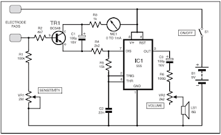
Circuit diagram :
Model Railway Short-Circuit Beeper Circuit Diagram

The rapid-acting acoustic short-circuit detector described here eliminates these problems. However, it requires its own power source, which is implemented here in the form of a GoldCap storage capacitor with a capacity of 0.1 to 1 F. A commonly available reed switch (filled with an inert gas) is used for the current sensor, but in this case it is actuated by a solenoid instead of a permanent magnet. An adequate coil is provided by several turns of 0.8–1 mm enamelled copper wire wound around a drill bit or yarn spool and then slipped over the glass tube of the reed switch. This technique generates only a negligible voltage drop. The actuation sensitivity of the switch (expressed in ampèreturns or A-t)) deter-mines the number of turns required for the coil. For instance, if you select a type rated at 20–40 A-t and assume a maxi-mum allowable operating current of 6 A, seven turns (40 ÷ 6 = 6.67) will be sufficient. As a rule, the optimum number of windings must be determined empirically, due to a lack of specification data. 

As you can see from the circuit diagram, the short-circuit detector is equally suitable for AC and DC railways. With Märklin transformers (HO and I), the track and lighting circuits can be sensed together, since both circuits are powered from a single secondary winding. 

Coil L1 is located in the common ground lead (‘O’ terminal), so the piezoelectric buzzer will sound if a short circuit is present in either of the two circuits. The (positive) trigger voltage is taken from the lighting circuit (L) via D1 and series resistor R1. Even though the current flowing through winding L1 is an AC or pulsating DC current, which causes the contact reeds to vibrate in synchronisation with the mains frequency, the buzzer will be activated because a brief positive pulse is all that is required to trigger thyristor Th1. The thyristor takes its anode voltage from the GoldCap storage capacitor (C2), which is charged via C2 and R2.  The alarm can be manually switched off using switch S1, since although the thyris-tor will return to the blocking state after C2 has been discharged if a short circuit is present the lighting circuit, this will not happen if there is a short circuit in the track circuit. C1 eliminates any noise pulses that may be generated. 

As a continuous tone does not attract as much attention as an intermittent beep, an intermittent piezoelectric generator is preferable. As almost no current flows during the intervals between beeps and the hold current through the thyristor must be kept above 3 mA, a resistor with a value of 1.5–1.8 kΩ is connected in parallel with the buzzer. This may also be necessary with certain types of continuous-tone buzzers if the operating current is less than 3 mA. The Zener diode must limit the operating voltage to 5.1 V, since the rated volt-age of the GoldCap capacitor is 5.5 V.
Read More..

PWM Discrete Generator Circuit and explanation

PWM waveforms are commonly used to control the speed of DC motors. The mark/space ratio of the digital wave-form can be defined either by using an adjustable analogue voltage level (in the case of a NE555 based PWM generator) or digitally using binary values. Digitally derived PWM waveforms are most often produced by the timer/counter modules in microcontrollers but if you do not want to include a microcontroller in your circuit it’s also quite simple to generate the signals using discrete logic components.Circuit diagram:

Discrete PWM Generator Circuit Diagram

An extension of the circuit shown can produce two PWM wave-forms from an 8-bit digital input word. Each signal has 15 values. The 8-bit word can be produced for example from an expansion board fitted in a PC or from an 8-bit port of a processor which does not have built-in PWM capability or from a laptop’s printer port. The mark/space ratio is only programmable up to 15/16 rather than 16/16; a binary input of 0000 produces a continuous low on both outputs turning both motors off.

Similar circuits often employ a dedicated ‘enable’ input to turn the motors off but it is not necessary in this design. The diagram shows the circuitry required to produce just one waveform. For the full two channel circuit it is necessary to use an additional 74HC193. The clock signal produced by the HCF4060 generator can be used to drive both channels and the free flip flop in the 74HC74 package can be used for the second channel (the corresponding pin numbers are shown in brackets). Altogether the entire two channel circuit can be built using just four ICs.
Read More..

Tuesday, November 11, 2014

LED flasher with Transistor circuits Diagram

These circuits only flash one or two LEDs. This is opposed to the light chaser circuits that can flash four or more. Of course, the simplest LED flasher is simply to use a flashing LED. The problem with that approach is you have no control over the flash rate, but it does have its use for eye catching displays for selling stuff. The circuits below give you that control, plus they can flash two LEDs alternately.
There are many possible applications for the circuits below, especially for kids, who love flashing lights. Heres some possible uses.
  • Railroad crossing signal for model railroads.
  • Safety blinkers for bicycles, etc.
  • Fun stuff for Halloween, like making those plastic Jack-O-lanterns blink (try using ultraviolet LEDs here).
  • Christmas decorations.
  • Blinkers to locate items in the dark.

Transistor LED flasher

This circuit has a lot going for it. For one thing, it only consists of two transistors, two capacitors and four resistors. That also means it consumes very little power. You can control the flash rate by changing the size of the 100k resistors (100k makes for a pretty slow rate). You can also control the duty cycle by using resistors of different values on the two sides. The 470 ohm resistors control the current through the LEDs. Normally you want to limit this to 20mA, but to conserve battery power, you may need to limit it even further. You can also connect several LEDs in series, instead of using only one for each side. With red LEDs (1 per side) and the values shown, the circuit draws about 11mA. Heres what the actual circuit looks like:


On this circuit, the green wires connect to the LEDs, but you can mount them on the actual circuit board for some applications. The picture is about twice actual size.
Read More..

Sunday, November 9, 2014

Car Reverse Horn

Most of people have there own vehicles.so I suppose this circuit will be very useful circuit for them.This circuit is a car reverse horn.If you can build your own circuit for your car I think that is great.Here I have used common Music generator IC UM 66.The out put voltage of UM66 is not enough to make a good car reverse horn so by using two transistors (BC148 and BEL187)I have increased it.


# This circuit operates with 12V power supply
# Build this circuit on a PCB to get good results
# use 8ohm speaker.
# Use only push to on switch. 
Read More..

Saturday, November 8, 2014

Voice Bandwidth Filter

This circuit passes frequencies in the 300Hz - 3.1kHz range, as present in human speech. The circuit consists of cascaded high-pass and low-pass filters, which together form a complete band-pass filter. One half of a TL072 dual op amp (IC1a) together with two capacitors and two resistors make up a second-order Sallen-Key high-pass filter. With the values shown, the cut-off frequency (3dB point) is around 300Hz. As the op amp is powered from a single supply rail, two 10kO resistors and a 10µF decoupling capacitor are used to bias the input (pin 5) to one-half supply rail voltage.

Circuit diagram:
voice-bandwidth-filter-circuit-diagram Voice Bandwidth Filter Circuit Diagram

The output of IC1a is fed into the second half of the op amp (IC1b), also configured as a Sallen-Key filter. However, this time a low-pass function is performed, with a cut-off frequency of about 3.1kHz. The filter component values were chosen for Butterworth response characteristics, providing maximum pass-band flatness. Overall voltage gain in the pass-band is unity (0dB), with maximum input signal level before clipping being approximately 3.5V RMS. The 560O resistor at IC1bs output provides short-circuit protection.
Read More..

Going for Gold Circuit Diagram

The title refers to a popular TV game show where the contestants each have a big button.  The  game show  host  asks  a  question and the first contestant to press their but-ton makes an illuminated indicator light up on their desk. The other contestants’ buttons  are automatically inhibited, so that everyone can see who was the first contestant to press their button, and so is allowed to answer the question. The project described here shows how to build a similar sortof  refereeing device yourself, using simple resources and without needing a microcontroller, which is  pretty rare these days! The basic circuit is for  just two contestants, but the modular design  means it can easily be expanded.

Circuit diagram :
 
Going for Gold Circuit Diagram

The diagram shows three buttons: S2 and S3  are the buttons for the two contestants, S1 is  the button for the host, which allows them to  reset the circuit before each fresh question.  The ‘brains’ of the circuit is IC1, a 4013 dual D-type flip-flop, of which only the Set and Reset  inputs are used here. This circuit can handle  quite a wide supply voltage range, from 3 to  15 V, and so the project can easily be run off a 4.5 V battery pack (the power consumption is minimal).

IC1 is armed by pressing S1 (reset). In this  state, the non-inverting outputs (pins 1 and  13) are at 0 and the inverting outputs (pins 12  and 12) are at 1. Hence line A is pulled high  by R1, since diodes D2 and D4 are not biased  on. If contestant 1 presses button S2, the  non-inverting output of flip-flop IC1a goes  to logic 1, and LED D1 lights via T1 to indicate that contestant 1 has pressed the but-ton. At the same time, the flip-flop’s invert-ing output goes to logic 0, making diode  D2 conduct. Line A is now pulled down to 0,  and consequently contestant 2’s button S3  can no longer trigger the second flip-flop.  The reverse happens if it is contestant 2 who  presses their button S3 first.

The circuit can be extended to 4 or 6 contest-ants (or even more) by adding a second or  third (or more) 4013 IC. All you have to do is  repeat the circuit (minus R1, R2, and S1) and connect to the A, B, Vdd, and 0 V lines on the right-hand side.
Read More..

Guitar Effect Pedal Power


A small box is fitted to the rear of the amplifier providing a 9V output for the effect pedal. The amplifier section gets 9V through a pedal switch. This power output and guitar signal input lines are combined into a single unit with multi-way cable connecting points as shown in the following figure. 
Guitar Effect Pedal Power diagram :

Guitar Effect Pedal Power Circuit Diagram
The circuit can be divided into two sections: power supply and signal handling. The power supply section is built around transformer X1, regulators 7805 and 7905, bridge rectifier comprising diodes D1 through D4, and a few discrete components. The signal-handling circuit is built around two OP27 op-amps (IC3 and IC4). The power supply of about 9V for the effect pedals is derived from step-down transformer X1. MOV1 is a metal-oxide varistor that absorbs any large spike in mains power.  IC 7905 (IC1) is a -5V low-power regulator. By using a 3.9V zener diode (ZD1) at its ground terminal, you get -8.9V output. The same technique is also applied to IC 7805 (IC2)-a +5V regulator to get 8.9V. Use good-quality components and heat-sinks for the regulators. This supply is more than enough for the five effect pedals.
The greater the voltage drop across the regulator, the lower the output current potential. Resistors R1 and R2 provide a constant load to ensure that the regulators keep regulating. Capacitors C3 through C8 ensure that the supplies are as clean as possible. It is very important to use proper heat-sinks for IC1 and IC2. Otherwise, these could heat up.

Working of the circuit is simple. The input signal stage uses a basic differentiation amplifier to accept the incoming signal and a voltage follower to buffer the output to the power amplifier. The differential amplifier is built around IC3. It works by effectively looking at the signals presented to its inputs. If the input signals are of different amplitudes, IC3 amplifies the difference by a factor determined by R4/R3 (where R4=R6 and R3=R5). If the input signals have same amplitudes, these are attenuated by the common-mode rejection ratio (CMRR) of the circuit. The value of CMRR is determined by the choice of the op-amp the auxiliary components used and circuit topology. You can use standard resistors.

With the values shown, you get an overall gain of unity. 
The combination of resistor R7 and C13 serves as a passive low-pass filter, progressively attenuating unwanted high-frequency signals. The second op-amp (IC4) forms a simple voltage follower (its output follows its input), providing a low output impedance to drive into the standard power amplifier.  Assemble the circuit on a general-purpose PCB and fit it to the rear of an amplifier. The unit must be compact, yet robust. So use a very sturdy aluminium extrusion for the cabinet in order to neatly house the assembled PCB.
To ensure simple operation, there are only three connections to the unit. First, mains power is tapped from the transformer. The second lead carries the 9V output to the amplifier. The third is the guitar signal input at the five-way socket for connection to the effect pedal.
Read More..