Showing posts with label level. Show all posts

Wednesday, November 19, 2014

Measure your stress level – Tension meter

If you, like so many other people in this day and age, arrive home from work stressed out and with the problems of the day still lingering,this simple little instrument will go a long way to relieving nervous tension.
Of the various types of feedback devices, probably the best approach for the amateur experimenter is the Galvanograph, better known as the Galvanic Skin Response Monitor. The instrument described here relies for its operation on changes in skin resistance in sympathy with changes in emotional state. An increase in tension level reduces skin resistance and, conversely, a decrease in tension is accompanied by an increase in skin resistance.
The correlation between emotional stress and skin resistance is still not fully understood. What is known, though, is that minute changes in the permeability of the skin produce corresponding voltage variations across two electrode pads attached to two fingers on the same hand.

Measure


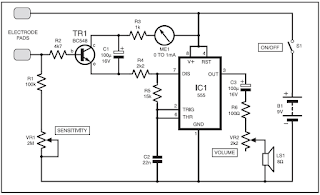
Tension Monitor meter circuit

These signal fluctuations are amplified and fed to an oscillator to produce an audible tone. A decrease in pitch therefore signifies a decrease in tension, and vice-versa. A visual indicator in the form of a panel meter also aids the user in monitoring tension levels. The monitor is quite sensitive to fluctuations. During use, a sudden moment of stress, even a deep sigh, will increase the pitch and cause a shift of the meter needle. Circuit Details In the circuit diagram of Fig.1, IC1 is configured as an astable multivibrator to drive an 8-ohm miniature speaker LS1 via capacitor C3, resistor R6 and volume control potentiometer VR2. The latter allows users to set a desired level and avoid it becoming a distraction.
Whereas the trigger input of IC1 is normally connected to the positive rail via a resistor in a conventional 555 oscillator, here it is connected via resistor R4 to the emitter of transistor TR1. The base of TR1 is connected between one electrode pad and the voltage divider formed by potentiometer VR1 and resistor R1. It will be seen that with the pads fitted to the fingers, the tone level will be dependent on the setting of VR1 and skin resistance. Resistor R2 in the transistor base is necessary should the pads be accidentally touched together. A 1mA meter is fitted in the collector line, along with R3, as a visual indicator. Although not essential or intended to measure current levels, it does help to emphasize fluctuations in emotional level.
The design of the pads is not critical. For the prototype, stripboard was used. The tracks were wired together at one end and connected to a 30cm length of twin lighting flex. The pads were then glued to Velcro straps. When the unit is first switched on, a highpitched tone should be heard, rapidly diminishing and ceasing. Turn the Sensitivity control VR1 to the minimum setting. Attach the electrodes to the fleshy pads of the first two fingers on the less-dominant hand with the Velcro straps, firmly but not tight. Rest the hand comfortably and keep it reasonably still, allowing half a minute for the pads to “bond”. Normally, at the minimum setting, the oscillator will hardly tick over, unless the user is in a high state of anxiety. Keep in mind that any form of stimulant, and that includes tea, coffee, alcohol and cigarettes, will reduce one’s capacity to relax. Rotate the control until a medium pitched tone is obtained and apply your relaxation technique. The monitor does not teach any method of meditation or relaxation; it only monitors the effectiveness of the technique applied. The tone should slowly diminish, with fluctuations as unconscious thoughts flit across the mind.When the sound ceases altogether, repeat the above procedure by increasing VR1. Twenty minutes is considered by therapists to be an adequate relaxation session.
Read More..

Thursday, November 13, 2014

LED Sound level display circuit by using IC LM3915

This circuit is about audio sound level LED display, indicator, monitor or you can say it “Audio VU (Volume Unite) Meter”.
This is a simple audio sound level LED display circuit diagram. The circuit is completely  based on  a single ic LM3915 from National Semiconductor. The LM3915 is a monolithic integrated circuit. It displays the audio sound level in terms of 10 LEDs and providing a logarithmic 3 dB/step analog display.

Audio sound level display circuit diagram


Fig: Circuit diagram of sound level display using ic LM3915
The audio sound level LED display circuit can operate from a single supply 3V to 25V. But I  suggest to use 9-12V. LED brightness can be controlled with a single pot( variable resistor) as shown 10K ohm in the circuit. Connect the audio input signal in Pin-5 of LM3915 from output of a audio device like output of audio amplifier or any other source.
The Pin-9 of LM3915 is to select dot or bar mode display. To make the circuit moving dot display instead of a bar graph display disconnect the Pin-9 from +V.
Read More..

Thursday, September 4, 2014

Water level alarm circuit


Here is a simple water level alarm schema that will produce an audible alarm when the water level reaches a preset level.The schema can be powered of a 3V battery and is very handy to use.


The schema is based on an astable multivibrator wired around IC1 (NE 555).The operating frequency of the astable multivibrator here will depend on capacitor C1, resistances R1,R2 and the resistance across the probes A&B.When there is no water up to the probes,they will be open and so the multivibrator will not produce oscillations and the buzzer will not beep.When there is water up to the level of probes,some current will pass through the water,the schema will be closed to some extend,and the IC will start producing oscillations in a frequency proportional to the value of C1,R1,R2 and the resistance of water across the probes.The buzzer will beep to indicate the presence of water up to the level of the sensing probes.


Notes.

* The schema can be powered of a 3V battery.
* Assemble the schema on a good quality PCB or common board.
* The probes can be made of two insulated copper Aluminiun wires.
* Place the probes at the position where you have to sense the leve

Read More..

Water Level Indicator Circuit

Simple, two-wire, remote monitoring unit, Three-LED level display, 9V battery powered
The whole project was developed on a friends request. Its purpose was to remotely monitor the water-level in a metal tank located in the attic by means of a very simple control unit placed in the kitchen, some floors below.

Mains requirements were:
  1. No separate supply for the remote schema
  2. Main and remote units connected by a thin two-wire cable
  3. Simple LED display for the main unit
  4. Battery operation to avoid problems related to mains supply and water proximity
  5. As the schema was battery operated a low current consumption was obviously welcomed
The very small remote unit is placed near the tank and measures the water level in three ranges by means of two steel rods. Each range will cover one third of the tank capacity:
  • Almost empty - signaled by means of a red LED (D3) in the control unit display
  • About half-level - signaled by means of a yellow LED (D2) in the control unit display
  • Almost full - signaled by means of a green LED (D1) in the control unit displa
Circuit diagram:
Water
Water-level Indicator Circuit Diagram

Circuit operation:
When the water-level is below the steel rods, no contact is occurring from the metal can and the rods, which are supported by a small insulated (wooden) board. The small schema built around IC1 draws no current and therefore no voltage drop is generated across R5. IC2A, IC2B and Q1 are wired as a window comparator and, as there is zero voltage at input pins #2 and #5, D3 will illuminate. When the water comes in contact with the first rod, pin #13 of IC1 will go high, as its input pins #9 to #12 were shorted to negative by means of the water contact. Therefore, R4 will be connected across the full supply voltage and the remote schema will draw a current of about 9mA. 

This current will cause a voltage drop of about 0.9V across R5 and the window comparator will detect this voltage and will change its state, switching off D3 and illuminating D2. When the water will reach the second rod, also pin #1 of IC1 will go high for the same reason explained above. Now either R3 and R4 will be connected across the full supply voltage and the total current drawing of the remote schema will be about 18mA. The voltage drop across R5 will be now about 1.8V and the window comparator will switch off D2 and will drive D1. The battery will last very long because the schema will be mostly in the off state. Current is needed only for a few seconds when P1 is pushed to check the water-level and one of the LEDs illuminates.
Parts:
R1 = 15K 1/4W Resistors
R2 = 15K 1/4W Resistors
R3 = 1K 1/4W Resistors
R4 = 1K 1/4W Resistors
R5 = 100R 1/4W Resistor
R6 = 47K 1/4W Resistor
R7 = 3.3K 1/4W Resistors
R8 = 3.3K 1/4W Resistors
R9 = 2.7K 1/4W Resistors
R10 = 15K 1/4W Resistors
R12 = 15K 1/4W Resistors
R13 = 3.3K 1/4W Resistors
R14 = 2.7K 1/4W Resistors
R15 = 2.7K 1/4W Resistors
D1 = 3mm Green LED
D2 = 3mm Yellow LED
D3 = 3mm Red LED
C1 = 470nF 63V Polyester or Ceramic Capacitor
J1 = Two ways output sockets
J2 = Two ways output sockets
P1 = SPST pushbutton
B1 = 9V PP3 Battery
Q1 = BC547 45V 100mA NPN Transistor
IC1 = 4012 Dual 4 input NAND gate IC
IC2 = LM393 Dual Comparator IC
Two steel rods of appropriate length
Notes:
  • The two steel rods must be supported by a small insulated (wooden) board
  • IC1 and R1-R4 are mounted on a small board placed near or on the steel rods support
  • The two-wire cable connecting the remote schema board to the main control board, i.e. J1 to J2, can be of any size and type (preferably thin for obvious reasons). It can be very long, if necessary.
  • The schema can be used also with non-metal tanks, provided a third steel rod having the height of the tank will be added and connected to pin #7 of IC1, R3, R4 and J1.
  • The 4012 chip was chosen because it contains two gates and was at hand, but you can use two of the gates contained into 4001, 4011, 4093, 4049, 4069 etc. chips, provided all inputs of each gate are tied together and all inputs of unused gates are connected to the positive rail, leaving output pins open.
Read More..

Sunday, August 17, 2014

Novel Liquid Level Sensor

Novel Liquid-Level Sensor Circuit diagram. Normally, the level of a liquid in a container is determined by sensing changes in the capacitance or resistance between a pair of electrodes that are immersed in the liquid. Generally speaking, this technique requires fairly complicated schemary to protect the electrodes against electrolysis (and associated corrosion). In addition, in many cases the liquid must be conductive for the measurement principle to actually be usable. The schema presented here shows that an alternative approach is possible.
Novel Liquid-Level Sensor Circuit diagram:
image
Novel Liquid-Level Sensor Circuit Diagram

Here we utilise the fact that a PTC resistor warms up in pro-portion to the amount of current flowing through it, with the result that its resistance increases. If a PTC resistor is immersed in a liquid, the additional warmth is dissipated in the liquid and the resistance remains nearly constant.

 If the level of the liquid drops below the immersion depth of the resistor, the change in the resistance can be easily sensed by a subsequent comparator stage. The PTC resistor should be isolated from the fluid into which it is immersed, in order to prevent undesirable electrolytic processes from taking place. A further improvement in the characteristics of the schema can be achieved by using a logic schema such as a micro controller to apply power to the schema only at predefined times and then switch off the power after sampling the comparator output.
Read More..

Monday, August 11, 2014

Water Level Alarm

Water Level Alarm schema diagram
More explanation about water level schema, please go to this page.

Description:
This schema will trigger with any fluid with a resistance under 900K between the maximum separation distance of the probes. Let me explain further. The schema uses a 4050B CMOS hex buffer working on a 5 volt supply.
Read More..