Showing posts with label alarm. Show all posts
Showing posts with label alarm. Show all posts
Thursday, November 20, 2014
Fire alarm with light sensor
Fire alarm can be made with a light sensor (LDR) as in the article with the title of Fire Alarm with this LDR sensor. Principles of fire detection Fire Alarm with LDR sensor is to detect the presence of smoke through the LDR. LDR in the series Fire Alarm does not stand alone in detecting a fire, but the LDR in the pair with the light shining on the LDR.
Hence, in the detected smoke from the fire then the intensity of light received by the LDR LDR decreases and eventually trigger an alarm system on a series of Fire Alarm with this LDR sensor. Part 2 that in the series of Fire Alarm with Sensor LDR are some of the sensors, tone generator, audio power.
Image Series Fire Alarm with Sensor LDR

Function Section of the Fire Alarm with Sensor LDR
Part of LDR and light sensor facing to fire smoke detection
Part trigger using transistors and regulators as a trigger tone generator 7805
Tone generator section with IC UM66
Power audio section uses an audio power IC TDA 2002 which is equipped with voleme control (R3)

Thursday, November 6, 2014
Security Alarm
Thwart any attempt of burglary in your house using this alarm circuit. When someone opens the door of your room, it sounds an alarm intermittently and flashes light as well. The circuit can also be used as an audio/visual alarm in case of fire or other emergency by momentarily pressing switch S3.
The circuit (refer Fig.1) is built around transformer X1, a standard bar magnet, reed switch S2, timer IC NE555 (IC1), opto-coupler IC MOC3020 (IC2), TRIAC BT136 and a few discrete components. Timer IC1 is wired as an astable multi-vibrator whose reset pin 4 is controlled by the reed switch. The reed switch fitted in the door frame acts as the sensor. A magnet is fixed on the door panel close to the reed switch.
Fig.1: Simple Security Alarm Circuit Diagram :

The reed switch consists of a pair of contacts on ferrous metal sealed in a glass envelope. The contacts may be normally-open (which close when a magnetic field is present) or normally closed type (which open when a magnetic field is applied). A normally open- type reed switch is used here.
When the door is closed, reed switch S2 is in open state. When the door is opened, the bar magnet moves away from reed switch S2. As a result, reset pin 4 of IC NE555 goes high. The high output at pin 3 of IC1 enables IC2. Pin 4 of IC2 is connected to the gate of TRIAC1. When the door is opened, bulb B1 flashes and the bell sounds (provided switch S4 is closed) indicating that the door has been opened. Flashing of the bulb and the alarm continue until the door is closed.
Assemble the circuit on a general purpose PCB and enclose in a suitable cabinet. Connect the call bell at the back side and the bulb at the front side of the cabinet. Install the unit on the door of the room as shown in Fig.2.
Fig.2: Reed Switch Fitting in Door :

The circuit is powered by mains supply.
Monday, November 3, 2014
Broken Charger Connection Alarm
Detects if a device is not properly connected to its supply Suitable for battery chargers, portable appliance supplies etc. The above circuit can be useful to detect if the load of any battery charger or plug-in adapter supply is not properly connected. The load can be a set of batteries to be charged or any other type of battery or low dc voltage operated device. The circuit can safely operate over a 3 to 15V range and 1A max. Current, provided the supply voltage is about one volt higher than the voltage required by the load.
The circuit is inserted between the supply and the load; therefore, until a trickle-charging current of at least 100µA is flowing towards the load, D1 and D2 will conduct. The forward voltage drop (about 1V) available across the Diodes drives Q2 into conduction and, consequently, Q1 will be cut-off. If no appreciable load is connected across the circuits output, Q2 will become cut-off, Q1 will conduct and the Piezo-sounder will beep.
Broken Charger Connection Alarm Circuit Diagram
| Parts | Description |
| R1 | 10K |
| R2 | 1K |
| R3 | 1K |
| Q1 | BC557 |
| Q2 | BC557 |
| D1 | 1N4007 |
| D2 | 1N4007 |
| D3 | Red LED |
| BZ1 | Piezo Sounder |
NOTE:
- An optional LED and its series limiting resistor can be wired in parallel to BZ1, as shown in dotted lines in the circuit diagram.
- In this case you may omit the Piezo-sounder in order to obtain a visual alert only.
Thursday, October 16, 2014
Make Relay Based Motorcycle Alarm Circuit Diagrams
You can Make Relay Based Motorcycle Alarm Circuit Diagrams. You can use them to protect your motorcycle - but they have many more applications. If you use relays with 6-volt coils - theyll protect your "Classic Bike". Both alarms are very small. The completed boards occupy about half a cubic-inch - 8 cc. The standby current is zero - so they wont drain your battery.
Relay Based Motorcycle Alarm Circuit Diagram 1 uses a SPCO/SPDT relay - but you really only need to use a SPST relay. If you are going to use the veroboard layout provided - youll need to use the style of relay specified. But you can build the alarm using whatever style of relay you have available.
Relay Based Motorcycle Alarm Circuit Diagram 1

Any number of normally-open switches may be used. Fit the mercury switches so that they close when the steering is moved or when the bike is lifted off its side-stand or pushed forward off its centre-stand. Use micro-switches to protect removable panels and the lids of panniers etc. When one of the trigger-switches is closed - the relay will energize and the siren will sound.
You can choose what happens next. If you build the circuit as shown, the siren will continue to sound until you turn it off - or until the battery is exhausted. But, if you leave out D3 - the siren will stop sounding immediately the trigger-switch is re-opened.
While youre within earshot of your machine - the former configuration is best. You can always turn off the alarm yourself. But if you are going to be away from your bike for any length of time - and you dont want to cause a nuisance - then the latter configuration is probably more suitable. If you include a SPST switch in series with D3 - you can select the behaviour that best suits the circumstances at any given time.
Relay Based Motorcycle Alarm Circuit Diagram 1a

Relay coils and some sounders produce high reverse-voltage spikes that will destroy sensitive electronic components. D1 and D2 are there to short-circuit these spikes before they can do any damage. Although there is nothing in the alarm circuit itself that could be damaged - I have no idea what other electronic equipment might be connected to the same power supply. So I included the two diodes as a precaution. If youre satisfied that theres nothing on your bike that might be damaged in this way - you can leave out the two diodes.
Relay Based Motorcycle Alarm Circuit Diagram 2 uses a DPCO/DPDT relay - but you really only need to use a DPST relay. If you are going to use the veroboard layout provided - youll need to use the style of relay specified. But you can build the alarm using whatever style of relay you have available.
Relay Based Motorcycle Alarm Circuit Diagram 2

Any number of normally-open switches may be used. Fit the mercury switches so that they close when the steering is moved or when the bike is lifted off its side-stand or pushed forward off its centre-stand. Use micro-switches to protect removable panels and the lids of panniers etc. When one of the trigger-switches is closed - the relay will energize and the siren will sound.
You can choose what happens next. If you build the circuit as shown, the siren will continue to sound until you turn it off - or until the battery is exhausted. But, if you leave out the (yellow) solder-bridge in the top left-hand corner of the diagram - the siren will stop sounding immediately the trigger-switch is re-opened.
While youre within earshot of your machine - the former configuration is best. You can always turn off the alarm yourself. But if you are going to be away from your bike for any length of time - and you dont want to cause a nuisance - then the latter configuration is probably more suitable. Connect a SPST switch in place of the (yellow) solder-bridge - and you can select the behaviour that best suits the circumstances at any given time.
Relay Based Motorcycle Alarm Circuit Diagram 2 a

Relay coils and some sounders produce high reverse-voltage spikes that will destroy sensitive electronic components. D1 and D2 are there to short-circuit these spikes before they can do any damage. Although there is nothing in the alarm circuit itself that could be damaged - I have no idea what other electronic equipment might be connected to the same power supply. So I included the two diodes as a precaution. If youre satisfied that theres nothing on your bike that might be damaged in this way - you can leave out the two diodes.
Whichever alarm you build - the circuit board and switches must be protected from the elements. Dampness or condensation will cause damage. Without the terminal blocks - the board is small. Ideally, you should try to find a siren with enough spare space inside to accommodate it. Fit a 1-amp in-line fuse as close as possible to the power source. This is Very Important. The fuse is there to protect the wiring - not the circuit board. Instead of using a key-switch you can use a hidden switch; or you could use the normally-closed contacts of a small relay. Wire the relay coil so that its energized while the ignition is on. Then every time you turn the ignition off - the alarm will set itself.
When the alarms are not sounding - the circuits use no current. This should make them useful in other circumstances - where a power supply is not readily available. Powered by dry batteries - with the relay and siren voltages chosen to suit - the alarms could be fitted almost anywhere.
Sourced By : Streampowers
Thursday, September 4, 2014
Water level alarm circuit
Here is a simple water level alarm schema that will produce an audible alarm when the water level reaches a preset level.The schema can be powered of a 3V battery and is very handy to use.
The schema is based on an astable multivibrator wired around IC1 (NE 555).The operating frequency of the astable multivibrator here will depend on capacitor C1, resistances R1,R2 and the resistance across the probes A&B.When there is no water up to the probes,they will be open and so the multivibrator will not produce oscillations and the buzzer will not beep.When there is water up to the level of probes,some current will pass through the water,the schema will be closed to some extend,and the IC will start producing oscillations in a frequency proportional to the value of C1,R1,R2 and the resistance of water across the probes.The buzzer will beep to indicate the presence of water up to the level of the sensing probes.
Notes.
* The schema can be powered of a 3V battery.
* Assemble the schema on a good quality PCB or common board.
* The probes can be made of two insulated copper Aluminiun wires.
* Place the probes at the position where you have to sense the leve
Saturday, August 30, 2014
Long range Burglar Alarm Using Laser Torch
Laser torch-based burglar alarms normally work in darkness only. But this long-range photoelectric alarm can work reliably in daytime also to warn you against intruders in your big compounds, etc. The alarm comprises laser transmitter and receiver units, which are to be mounted on the opposite pillars of the entry gate. Whenever anyone enters to interrupt the transmitted laser beam falling on the receiver, the buzzer in the receiver schema sounds an alarm.
The range of this burglar alarm is around 30 metres, which means you can place the transmitter and the receiver up to 30 metres apart. Since the laser torch can transmit light up to a distance of 500 metres, this range can be increased by orienting the phototransistor sensor properly. To avoid false triggering by sunlight, mount the phototransistor sensor such that it doesn’t directly face sunlight.
Long-range Burglar Alarm Using Laser Torch
The transmitter schema is powered by 3V DC. The astable multivibrator built around timer 7555 (IC1) produces 5.25kHz frequency. CMOS version of timer 7555 is used for low-voltage operation. The body of the laser torch is connected to the emitter of npn transistor T1 and the spring-loaded lead protruding from inside the torch is connected to the ground.
The receiver schema is powered by 12V DC. It uses photoDarlington 2N5777 (T2) to sense the laser beam transmitted from the laser torch. The output beam signals from photoDarlington are given to the two-stage amplifier followed by switching schema, etc. As long as the laser beam falls on photoDarlington T2, relay RL1 remains un-energised and the buzzer does not sound. Also, LED1 doesn’t glow.
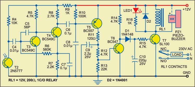
Fig. 2: Receiver schema
When anyone interrupts the laser beam falling on photoDarlington T2, npn transistor T6 stops conducting and npn transistor T7 is driven into conduction. As a result, LED1 glows and relay RL1 energises to sound the buzzer for a few seconds (determined by the values of resistor R15 and capacitor C10). At the same time, the large indication load (230V AC alarm for louder sounds or any other device for momentary indication) also gets activated as it is connected to 230V AC mains via normally opened (N/O) contact of relay RL1.
Sourced By: EFY Author ; Pradeep G.
Alarm using your own Voice
This alarm plays your prerecorded voice message. It is built around the readily available quartz clock. Take the buzzer out of the quartz clock and connect its positive terminal to pin 1 and negative terminal to pin 2 of optocoupler IC MCT2E (IC2). Pin 4 of IC2 is grounded and pin 5 is connected to trigger pin 2 of monostable multivibrator IC 555 (IC3) as shown in Fig. 2.
Fig. 1: Voice recording schema
Fig. 1 shows the schema for recording your voice message. When you press switch S2, it plays the meassage. The control schema shown in Fig. 2 avoids the need for pressing switch S2 and thereby sounding the voice alarm automatically at the preset time.
Connect points A and B of the recording schema to the corresponding points A and B of the control schema. After making the connections, press record switch S1 to record your 6-second voice message through condenser microphone. Set the desired alarm time in quartz clock. At the time of alarm, buzzer terminals provide voltage to the internal LED of optocoupler IC2. This results in conduction of internal transistor of IC2, and its collector voltage at pin 5 drops to trigger IC3. The output of IC3 goes high for approximately 6 seconds. During this period, the prerecorded message is heard continuously. The message repeats every 6 seconds. The sound is loud enough in a room.
Fig. 2: Voice control schema
The schema operates off 3 volts and it can be easily fitted in a small box and fixed on the back side of the alarm quartz clock.
Sourced by: EFY Author: Naga Babu Araya
Tuesday, August 26, 2014
Alarm Sound with Control Switch
The heart of this circuit is IC No. 555. When the alert sound was working, even though the switch will continue to be the same, the sound still does not stop immediately.But it will stops automatically, when a set time period,Depending on the resistance of R3, the circuit so I set a time period equal to 1M for 1 minute 6 seconds.
| Alarm Sound with Control Switch |
The output of IC 555 is triggered by a positive voltage on pin 2,when all switches are connected together.When the something switch is cut off pin 2, it will be negative voltage and the trigger IC 555 will stop. The C1, C4 to protects a noise signal from either switch, which may cause the alarm to be up. This circuit can be used with power supply from 5V to 15V depending on relay sure enough.
Saturday, August 23, 2014
Simple Car alarm Wiring diagram Schematic Using 555 Timer
This is a Simple Car alarm Circuit Diagram Using 555 Timer.In this simple schema 555 timer produces a guaranteed delay, allowing the driver to deactivate the alarm and the elimination of a control switch vulnerable outside.The RCS prevents triggering a timer timer B, unless B is triggered by timer switches strategically located detector.
Simple Car alarm Circuit Diagram Using 555 Timer
Friday, August 22, 2014
Security alarm

This is Security alarm .If somebody disconnected the wire loop The speaker will generate a sound.I have used a schema for my land.Then when a robber enter for my land i can know it earlier.when you setup this set the wire loop at the height of 1 feet from the ground.

Note
# Build this schema on a pcb
# use a thin coil as the wire loop
Wednesday, August 20, 2014
Car Alarm Arming Horn Beep Canceller
This is a simple Car Alarm Arming Horn Beep Canceller schema Diagram. Its a great convenience that most modern cars come with a built in alarm, however it is nothing but noise pollution that the horn sounds when the alarm is armed. Disconnecting the alarm system from the horn relay will eliminate this, but prevent the horn from sounding in the even of an actual alarm. This schema serves to silence the arming beep yet maintain the alarm by introducing a small delay into the signal. It sits between the alarm and horn relay. The alarm must provide a constant horn signal for at least 3 seconds before the horn relay is activated. That way the quick "beep" will never activate the horn relay, while the constant alarm signal will.
Car Alarm Arming Horn Beep Canceller Circuit Diagram
| C1 | 1 | 0.01uF Ceramic Disc Capacitor | |
| C2 | 1 | 100uF 35V Electrolytic Capacitor | |
| R1 | 1 | 1K 1/4W Resistor | |
| R2 | 1 | 10K 1/4W Resistor | |
| R3 | 1 | 15K 1/4W Resistor | |
| R4 | 1 | 470 Ohm 1/4W Resistor | |
| D1, D3, D4 | 3 | 1N4004 Rectifier Diode | |
| D2 | 1 | Red LED | |
| U1 | 1 | 555 Timer IC | |
| K1 | 1 | SPST 12V Automotive Relay | |
| MISC | 1 | Board, Wire, Socket For U1, Case |
Monday, August 11, 2014
Water Level Alarm

Description:
This schema will trigger with any fluid with a resistance under 900K between the maximum separation distance of the probes. Let me explain further. The schema uses a 4050B CMOS hex buffer working on a 5 volt supply.
Fridge door Alarm
The schema, enclosed in a small box, should be placed in the fridge near the lamp (if any) or close to the opening. With the door closed, the interior of the fridge is in dark, the photo resistor R2 presents a high resistance (>200K) thus clamping IC1 by holding C1 fully charged across R1 and D1. When a beam of light enters from the opening, or the fridge lamp lights, the photo resistor lowers its resistance (<2k)>

Parts:
R1______________10K 1/4W Resistor
R2_____________Photo resistor (any type)
R3_______________2M2 1/4W Resistor
R4_______________1M 1/4W Resistor
C1______________10µF 25V Electrolytic Capacitor
C2_____________100nF 63V Polyester Capacitor
D1____________1N4148 75V 150mA Diode
IC1,IC2_________7555 or TS555CN CMos Timer ICs
BZ1___________Piezo sounder (incorporating 3KHz oscillator)
B1____________3V Battery (2 x 1.5V AA, AAA or smaller type Cells in series)
Notes:
* Delay time can be varied changing C1 and/or R3 values.
* Beeper repetition rate can be varied changing C2 and/or R4 values.
* Stand-by current drawing: 150µA.
* Place the schema near the lamp and take it away when defrosting, to avoid schema damage due to excessive moisture.
* Do not put this device in the freezer.
Read More..
Parts:
R1______________10K 1/4W Resistor
R2_____________Photo resistor (any type)
R3_______________2M2 1/4W Resistor
R4_______________1M 1/4W Resistor
C1______________10µF 25V Electrolytic Capacitor
C2_____________100nF 63V Polyester Capacitor
D1____________1N4148 75V 150mA Diode
IC1,IC2_________7555 or TS555CN CMos Timer ICs
BZ1___________Piezo sounder (incorporating 3KHz oscillator)
B1____________3V Battery (2 x 1.5V AA, AAA or smaller type Cells in series)
Notes:
* Delay time can be varied changing C1 and/or R3 values.
* Beeper repetition rate can be varied changing C2 and/or R4 values.
* Stand-by current drawing: 150µA.
* Place the schema near the lamp and take it away when defrosting, to avoid schema damage due to excessive moisture.
* Do not put this device in the freezer.
Saturday, August 9, 2014
Wire Break Alarm With Delay Circuits Wiring diagram
Simple Wire-Break Alarm With Delay Alarm and Security Here is a simple schema of wire-break alarm that activates after a delay of 15 to 30 seconds. When the thin-wire loop running across the entrance door is broken, the alarm sounds after a delay of 15 to 30 seconds, the time period set through VR1. Thus the occupants get sufficient time to lock the room from the outside and catch the thief.
The schema uses CD4060, which is a 14-stage ripple-carry binary counter/divider and oscillator. It is wired as a timer here and does not need input pulse for trigger. CD4060 gets activated as soon as the power supply is switched on. Output O13 of CD4060 goes high after the lapse of preset delay set through VR1. Transistor SL100 (T2) is wired as a switch to power the timer section built around CD4060. When the wire loop is closed, transistor T2 does not conduct. So power to the timer schema is not available and the piezo buzzer does not sound.
Wire-Break Alarm With Delay Circuit Schematic

On the other hand, when the wire loop is broken by some intruder, transistor T2 conducts to power the schema and the piezobuzzer sounds after 15 to 30 seconds. IC1 can be reset by connecting the wire loop or interrupting the supply. The schema works off regulated 9V-12V. Assemble it on a general-purpose PCB and enclose in a metallic or plastic box of appropriate size. Connect piezobuzzer PZ1 through external wires and complete the installation.
Subscribe to:
Posts (Atom)
