Showing posts with label laser. Show all posts
Showing posts with label laser. Show all posts
Saturday, August 30, 2014
Long range Burglar Alarm Using Laser Torch
Laser torch-based burglar alarms normally work in darkness only. But this long-range photoelectric alarm can work reliably in daytime also to warn you against intruders in your big compounds, etc. The alarm comprises laser transmitter and receiver units, which are to be mounted on the opposite pillars of the entry gate. Whenever anyone enters to interrupt the transmitted laser beam falling on the receiver, the buzzer in the receiver schema sounds an alarm.
The range of this burglar alarm is around 30 metres, which means you can place the transmitter and the receiver up to 30 metres apart. Since the laser torch can transmit light up to a distance of 500 metres, this range can be increased by orienting the phototransistor sensor properly. To avoid false triggering by sunlight, mount the phototransistor sensor such that it doesn’t directly face sunlight.
Long-range Burglar Alarm Using Laser Torch
The transmitter schema is powered by 3V DC. The astable multivibrator built around timer 7555 (IC1) produces 5.25kHz frequency. CMOS version of timer 7555 is used for low-voltage operation. The body of the laser torch is connected to the emitter of npn transistor T1 and the spring-loaded lead protruding from inside the torch is connected to the ground.
The receiver schema is powered by 12V DC. It uses photoDarlington 2N5777 (T2) to sense the laser beam transmitted from the laser torch. The output beam signals from photoDarlington are given to the two-stage amplifier followed by switching schema, etc. As long as the laser beam falls on photoDarlington T2, relay RL1 remains un-energised and the buzzer does not sound. Also, LED1 doesn’t glow.
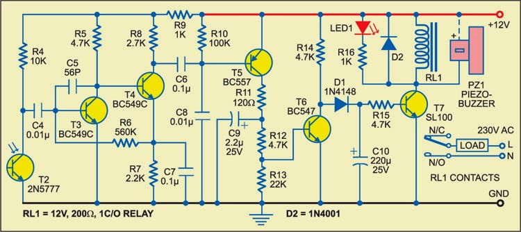
Fig. 2: Receiver schema
When anyone interrupts the laser beam falling on photoDarlington T2, npn transistor T6 stops conducting and npn transistor T7 is driven into conduction. As a result, LED1 glows and relay RL1 energises to sound the buzzer for a few seconds (determined by the values of resistor R15 and capacitor C10). At the same time, the large indication load (230V AC alarm for louder sounds or any other device for momentary indication) also gets activated as it is connected to 230V AC mains via normally opened (N/O) contact of relay RL1.
Sourced By: EFY Author ; Pradeep G.

Friday, August 15, 2014
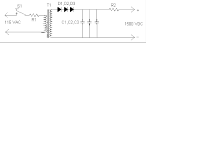
Laser Power Supply Circuit Schematic
Notes
1. T1 is an ordinary 9V 1A transformer connected backwards for step up.
2. R1 MUST be installed on a LARGE heatsink. A good heatsink is the metal case the supply is built in.
3. R2 Protects the laser tube from excess current. It should be soldered directly to the anode terminal on the tube. To find R2, start with a 500K 10W resistor and work down until the tube lights and remains stable.
4. If you have trouble with the tube not starting easily, use a longer anode lead that is wrapped around the tube.
5. Depending on the transformer you use, the schema may or may not work. I cannot guarantee the operation of this schema. Build at your own risk. Some transformers contain very few secondary windings which will quickly saturate the core and basically act like a direct short. The more secondary windings (that is, primary in this schema) the better.
Via
Subscribe to:
Posts (Atom)
