Showing posts with label switch. Show all posts

Tuesday, November 4, 2014

Video Switch for Intercom System

Nowadays a lot of intercom units are  equipped with video cameras so that you can  see as well as hear who is at the door. Unfortunately, the camera lens is perfectly placed  to serve as a sort of support point for people  during the conversation, with the result that  there’s hardly anything left see in the video  imagery.  One way to solve this problem is to install two cameras on the street side instead only  one, preferably some distance apart.

If you  display the imagery from the two cameras  alternately, then at least half of the time you  will be able to see what is happening in front  of the door. Thanks to the video switch module described  here, which should be installed on the street  side not too far away from the two cameras,  you need only one monitor inside the house and you don’t need to install any additional video cables.
 
Video Switch for Intercom System Circuit diagram:
Intercom


Along with a video switch, the circuit includes  a video amplifier that has been used with  good results in many other Elektor projects,  which allows the brightness and the contrast  to be adjusted separately. This amplifier is  included because the distance between the  street and the house may be rather large, so it is helpful to be able to compensate for cable attenuation in this manner.  The switch stage is built around the well  known 4060 IC, in which switches IC2a and  IC2d alternately pass one of the two signals to  the output.

They are driven by switches IC2b and IC2c, which generate control signals that  are 180 degrees out of phase. The switching rate for the video signals is  determined by a clock signal from an ‘old  standby’ 555 IC, which causes the signals to  swap every 2 seconds with the specified com ponent values.
 
Naturally, this circuit can also used in many other situations, such as where two cameras are needed for surveillance but only one video cable is available.
 
Read More..

Thursday, October 30, 2014

Project Mini RS232 Data Switch Circuit Diagram

This is the Project of Mini RS232 Data Switch Circuit Diagram. Only simple materials and a little bit of skill are needed to build an RS232 switch. All that you need are two 9-way sub-D plugs with solder pins, a small piece of sheet aluminium, two sets of screw retainer posts, a 4-pole double-throw switch, a strain relief sleeve and a suitable plastic connector shell for a 25-way sub-D connector, with both in-line and right-angle cable entries (such as Conrad Electronics #711322). What is important is that the side cable entry together with its associated strain relief leaves enough room for the switch. If necessary, you may have to cut away a few square millimetres of the sidewall or a few ribs of the plastic shell.

Project image :
 Mini
Mini RS232 Data Switch Image

The switch is operated via the in-line cable opening, as can be seen from the photo. A suitable switch with an overall length of 29 mm can be found in the Conrad catalogue under order number 708232. The only modification that must be made to the connector shell is to drill two holes for the retaining screws for the switch (M2.6 screws) at a spacing of 24 mm.

Mini RS232 Data Switch Circuit diagram :

Mini
Mini RS232 Data Switch Circuit Diagram

Connect the two sub-D connectors together using the piece of aluminium and the screw retainer posts. Then solder the cable to the connectors and the switch as indicated. The two connectors are wired somewhat differently. While the upper sub-D plug is connected 1:1 with the input cable (with the switch in the appropriate position), the DCD, DTR, DSR and RI pins of the lower connector are left open. This is because RTS and CTS are fully sufficient for handshaking, as long as DTR and DSR are connected to each other. The only leads that are switched are RXD, RTS, TSD and CTS. The ground potential is fed from the cable to both connectors. After everything has been properly soldered together, you can fit everything into the cable shell as shown.
Read More..

Friday, October 24, 2014

Toggle Switch with IR

Toggle switch in this article is a series of toggle switches that are controlled by infrared light. The series toggle switch is made from a combination of data flip-flop CD4013 2 units. Receiver circuit of the infrared light signals arranged with infrared receiver as found on television remote receiver. Infrared signal from remote is used as clock signals and data to the data flip-flop first. then the second flip-flop data set as a toggle flip-flop toggle the output signal is used to drive the relay. for more details can be seen in thethe following image .


Toggle


Series Toggle Switch With Infra Red (IR) that is required to supply voltage range of 12VDC and the output of Toggle Switch With Infra Red (IR) is dapt used to turn on the lights or other electronic devices with DC or AC voltage source. Series Toggle Switch With Infra Red (IR) was isolated from the load that is placed for use as the final relay.
Read More..

Friday, October 17, 2014

Simple Mat Switch Circuit

This simple circuit produces a warning beep when somebody crosses a protected area in your home or office. The switch, hidden be-low the floor mat, triggers the alarm when the person walks over it.

The circuit uses a conductive foam as the switch. It can be two small pieces of conductive pads usually used to pack sensitive ICs as antistatic cover. Alternatively, you can make the switch by coating conducting carbon ink on two small pieces of a copper-clad board.

Simple Mat Switch Circuit diagram :

Link


Simple Mat Switch Circuit Diagram

When the circuit is in standby mode, transistor T1 does not conduct, since its base is floating. When the person walks, the switch is pressed and current flows through R1 and the switch to provide positive bias to transistor T1. Transistor T1 conducts and its collector voltage drops, which acts as a negative trigger input for the monostable wired around IC NE555 (IC1).

IC1 outputs a pulse of fifty-seconds duration with preset values of R4 and C3. This pulse is applied to the buzzer through transistor T2. The buzzer sounds a warning beep on unauthorised entry. The pulse duration can be changed to the desired value by changing the values of R4 and C3. Resistor R2 in the circuit makes the trigger pin of IC1 high to prevent false triggering.

Assemble the circuit on a general-purpose PCB and enclose in a plastic case. Use a 9V battery to power the circuit. Connect the touchpad switch with the PCB and hide under the mat at the entrance. The PCB can be mounted on the nearby wall.

Make the switch carefully using conducting foam or copper clad coated with conducting ink. Place the two pieces with their conducting surface facing each other. Solder carefully a thin copper electric wire and ensure that it makes contact when the two plates touch together on pressing. Provide two 1cm rubber tabs between the plates to avoid touch in the standby mode.
Read More..

Thursday, October 16, 2014

Simple Sound Activated Lamp Relay Switch

This simple Sound-Activated Lamp circuit shown int the schematic diagram actives the switch using sound. We can use this circuit for various applications, such as automatic (sound-controlled) disco light or car’s LED light show.  The Q1 amplify the audio from mic. The R1 is used to adjust the peak of signal to greater than about 0.7 volts, act as sensitivity adjuster. A certain level, the signal coming from microphone, after amplification by Q1, will trigger the SCR and light lamp I1. If we change the lamp with a relay, then we can get a sound-activated relay/switch, which can be used to control more powerful / high wattage high voltage lamps. If we use a relay, place a 1N4007 diode in parallel with the relay coil to prevent the back-emf from  relay coil destroying the SCR.

 Sound-Activated Lamp Circuit Diagram

 sound-activated lamp circuit diagram

Read More..

Tuesday, September 9, 2014

Light Switch Circuit Diagram

circuit
The series of light switches this time slightly different from the voltage of work. The series of light switches can work directly on the AC power network. Light switches are using the main component of TRIAC and LDR. The circuit is very simple and the components were sold in the market.
Read more
Read More..

Saturday, September 6, 2014

Simple Buffered Analog Switch Wiring diagram Schematic

This is the Diode–transistor logic and Transistor–transistor logic Simple Buffered Analog Switch Circuit Diagram. This analog switch uses the 2N4860 JFET for its 25 ohm ron and low leakage. The LM102 serves as a voltage buffer. This schema can be adapted to a dual trace oscilloscope chopper. The DS7800 monolithic IC provides adequate switch drive controlled by DTL/TTL logic levels.

Buffered Analog Switch Circuit Diagram


Buffered

Read More..

Friday, September 5, 2014

Touch Switch Using FET

The series of touch this switch be an Touch Switch made ​​using FET. This circuit serves to activate electronic devices only when we touch touch sensors.
Once we release a touch to the sensor, the electronic device that is connected is turned off again. The series of touch switch or touch switch is very simple, composed only of a FET, resistor and capacitor. The series of touch switches / touch switches work with source voltage 12VDC. Detailed series of touch switches / touch switch can be seen in thethe following figure .

FET Touch Switch
FET

The series of touch switches / touch switch can only be used to illuminate DC, 12V DC lamp when it replaced the relay, the circuit can be used safely to load the AC network. Sensor touch to this series was made with 2 pieces of plate are arranged close together (within 1-2mm).
Read More..

Tuesday, August 26, 2014

Alarm Sound with Control Switch


The heart of this circuit is IC No. 555. When the alert sound was working, even though the switch will continue to be the same, the sound still does not stop immediately.But it will stops automatically, when a set time period,Depending on the resistance of R3, the circuit so I set a time period equal to 1M for 1 minute 6 seconds.
Alarm
Alarm Sound with Control Switch

The output of IC 555 is triggered by a positive voltage on pin 2,when all switches are connected together.When the something switch is cut off pin 2, it will be negative voltage and the trigger IC 555 will stop. The C1, C4 to protects a noise signal from either switch, which may cause the alarm to be up. This circuit can be used with power supply from 5V to 15V depending on relay sure enough.
Read More..

Sunday, August 24, 2014

Simple Sound Activated Switch

Simple Sound Activated Switch Circuit diagram : Control by sound may be very useful,  not just on a robot but also for a bit  of home automation, for example a  sound activated light responding to a  knock on the door or a hand clap. The  light will be automatically switched  off after a few seconds. An alternative  use is burglar protection — if someone  wants to open the door or break some-thing the light will come on, suggesting  that someone’s at home. The schema can work from any 5– 12 VDC regulated power supply pro-vided a relay with the suitable coil voltage is used.
 
Simple Sound Activated Switch Circuit diagram :


Sound Activated Switch Circuit Diagram

When you first connect the supply  voltage to the schema, the relay will  be energised because of the effect of capacitor C2. Allow a few seconds for  the relay to be switched off. You can  increase or decrease the ‘on’ period  by changing the value of C2. A higher  value results in a longer ‘on’ period,  and vice versa. Do not use a value  greater than 47 µF. Biasing resistor R1 determines to a  large extent the microphone sensitivity. An electret microphone usually has  one internal FET inside which requires  a bias voltage to operate. The optimum  bias level for response to sound has to  be found by trial and error.
 
All relevant electrical safety precautions should be observed when connecting mains powered loads to the relay contacts.
Read More..

Thursday, August 14, 2014

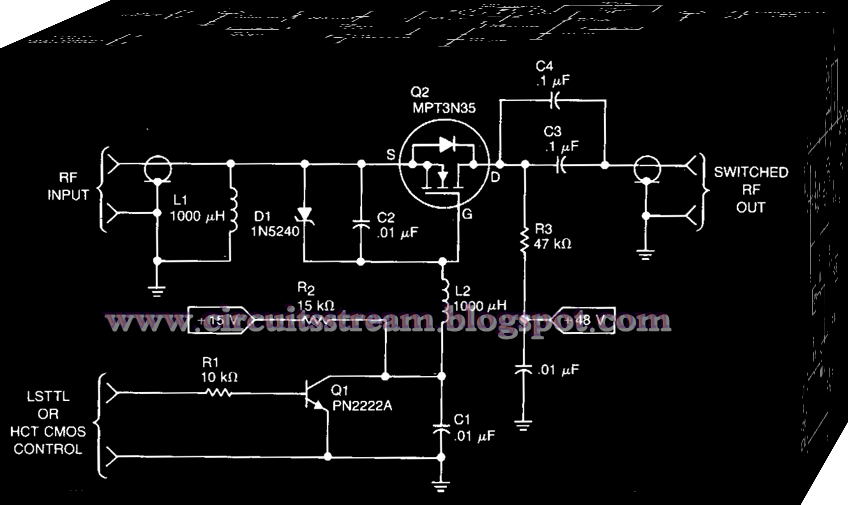
Simple Rf Power Switch Wiring diagram Schematic

This is a Simple Rf Power Switch Circuit Diagram. This Rf power switch operates at 1. 7 MHz with a 50-V source and load. Its on loss is 0.2 dB and its off isolation is 30 dB. It provides 40-W PEP, 45 VrEAK and 0.9 APEAK· The control input can come from CMOS, TTL, LS, etc., to turn on Q1, which turns on Q2, a TMOS MTP3N35.

Simple Rf Power Switch Circuit Diagram


Simple Rf Power Switch Circuit Diagram

Read More..