Thursday, August 28, 2014
Browse »
home»
amplifier
»
circuit
»
current
»
diagram
»
shunt
»
simple
»
Simple Current Shunt Amplifier Wiring diagram Schematic

Simple Current Shunt Amplifier Wiring diagram Schematic
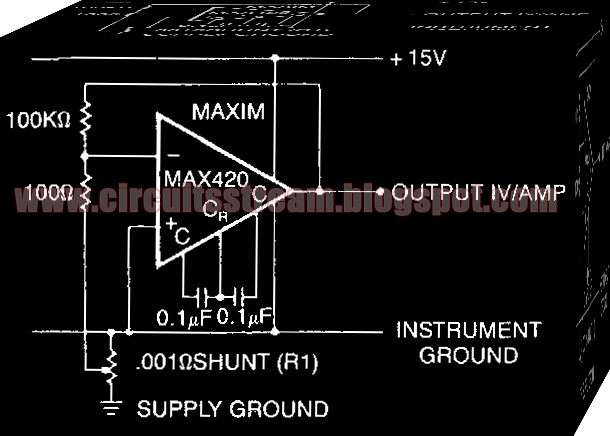
This is a Simple Current Shunt Amplifier Circuit Diagram. Current sense amplifiers (also called current shunt amplifiers) are special-purpose amplifiers that output a voltage proportional to the current flowing in a power rail.
Simple Current Shunt Amplifier Circuit Diagram

They utilize a "current-sense resistor" to convert the load current in the power rail to a small voltage, which is then amplified by the current-sense amplifiers.This schema measures the power -supply current of a schema without really having a current shunt resistor: R1 is only 3 em of #20 gauge copper wire.
A length of the power distribution wiring can be used for Rl. The MAX420`s CMVR includes its own negative power supply; therefore, it can both be powered by and measure current in the ground line.
Subscribe to:
Post Comments (Atom)
No comments:
Post a Comment