Showing posts with label amplifier. Show all posts

Thursday, November 20, 2014

High HiFi Power Amplifier with MOSFET

Circuit amplifier "High Power HiFi Power Amplifier With MOSFET" is capable of giving the output power to the load speakers 240Watt and 380Watt 8Ohm to load 4Ohm speakers.

Voltage source to a series of power amplifiers "High Power HiFi Power Amplifier With MOSFET" This is a CT 25V 50V 25V to 50V CT of transformer CT. In making this power amplifier needs to be installed heatsinks on the power amplifier (MOSFET) in order to avoid excessive heat. The series of power supply to power amplifer can use the transformer 5A-20A and 35A mounted diode bridge and capacitors for a minimum of 2x 10.000uF electrolit. Details for the power amplifier circuit can be seen in the following figure.


High

High Power Series HiFi Power Amplifier With MOSFET can modify to increase power output by doubling the final power amplifier is based on the diiginkan. Power generated from doubling the final power amplifier will also double its power output of power amplifier circuit "High Power HiFi Power Amplifier With MOSFET" it.
Read More..

Saturday, November 15, 2014

60 WATT AMPLIFIER CIRCUIT

STK4038 is an integrated AF power amplifier that can deliver 60 watts of output power into a 4 ohm load. The internal fixed current circuitry reduces switch ON/OFF clicks. The IC supports the addition of external circuits for thermal shutdown, pop noise reduction, output short circuit protection etc. This circuit is based on datasheet and it includes a Zobel network ( called filter section ) which improves the high frequency stability of the amplifier.
The 60 watt amplifier shown below is designed based on the datasheet and performs very well. Capacitor C1 is the input DC decoupling capacitor which blocks any DC level present in the audio input and C12 is the input by-pass capacitor. R1 is the input resistor.C10 and C8 are the ripple filter capacitors for the positive and negative power supply rails. R9 and R7 are the current limiting resistors for the internal driver stage while C11 and C3 are their corresponding filter capacitors. Resistor R6 feeds back a portion of the output signal to the inverting input (pin2). Gain of the amplifier depends on the value of R6. C9 and R2 forms a Zobel network which improves the high frequency stability of the amplifier.

Circuit Diagram


Points to Remember

  • A good quality PCB improves the performance of the circuit.
  • Maximum supply voltage for STK4038 is +/- 57V DC.
  • K1 is a 4 ohm / 75 watt loud speaker.
  • While using 4 ohm speaker as the load, the power supply must not exceed +/- 32V DC.

Read More..

Thursday, November 13, 2014

Photovoltaic Transimpedance Amplifier Circuit Diagram

Photovoltaic
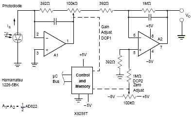
The following schematic shows the Photovoltaic Transimpedance Amplifier Circuit Diagram. This design combines two Intersil X9258T digitally controlled potentiometers with an AD822 low noise dual op amp to create a flexible, digitally calibrated, wide dynamic range transimpedance amplifier topology that can be used with virtually any photovoltaic detector technology. The amplifier output is given by:

Vo = Is(1MΩ) ((1+P1)/(256-P1))

Where P1 is the 8-bit (0 to 255) digital value written to DCP1. For more detail information on Photovoltaic Transimpedance Amplifier Circuit Diagram, download the following file.

Read More..

Friday, November 7, 2014

50 W Power Amplifier Circuit using STK084

50W

This is the circuit diagram of 50W power amplifier circuit which built based on single power amplifier chip of STK084. Its an well-known old IC for audio frequency (AF) amplifier.

This circuit requires dual polarity / split power supply with maximum supply of ± 50. The recommended supply is ± 35 / 2-3A DC current. You may use this split power supply circuit for the amplifier. Use 28V center tap transformer to get about ± 36V output.

Technical Details:
Power output: 50W
RL : 8 Ohm
TDH : 0.2 %
Rin : 52K
Gain : 26.4 dB
Noise : 0.3 mV

Take a note that heatsink is required to be mounted on the power IC since it will going to hot when operated and deliver high power output (high audio volume level).
Read More..

Wednesday, November 5, 2014

High Voltage 3 Watt Audio Power Amplifier

The LM4954 is an audio power amplifier primarily designed for demanding applications in mobile phones and other portable communication device applications. It is capable of delivering 2.4 Watts of continuous average power to an 8 BTL load with less than 1% THD+N from a 7VDC power supply. Boomer audio power amplifiers are designed specifically to provide high quality output power with a minimal number of external components. The LM4954 does not require output coupling capacitors or bootstrap capacitors, and therefore is ideally suited for lower-power portable applications where minimal space and power consumption are primary requirements.

High Voltage 3 Watt Audio Power Amplifier Circuit Diagram
Amplifier

The LM4954 features a low-power consumption global shutdown mode which is achieved by driving the shutdown pin with logic low. Additionally, the LM4954 features an internal thermal shutdown protection mechanism.
The LM4954 contains advanced pop & click circuitry which eliminates noises that would otherwise occur during turn-on and turn-off transitions.
The LM4954 is unity-gain stable and can be configured by external gain-setting resistors.

Key Specification
Wide Power Supply Voltage Range 2.7 <= VDD <= 9V
Output Power: VDD = 7V, 1% THD+N 2.4W (typ)
Quiescent power supply current 3mA (typ)
PSRR: VDD = 5V and 3V at 217Hz 80dB (typ)
Shutdown power supply current 0.01µA (typ)

Features:

  • No output coupling capacitors, snubber networks or bootstrap capacitors required
  • Unity gain stable
  • Externally configurable gain
  • Ultra low current active low shutdown mode
  • BTL output can drive capacitive loads up to 100pF
  • "Click and pop" suppression circuitry
  • 2.7V - 9.0V operation
  • Available in space-saving microSMD package
  • Applications

  • Mobile Phones
  • PDAs


  • Read More..

    Monday, November 3, 2014

    200 watts amplifier TDA2030

    200 watts amplifier TDA2030

    https://blogger.googleusercontent.com/img/b/R29vZ2xl/AVvXsEiCyNenzULK-Iojm901hyB7Hlp-riCc24ExQd3DVzzVQ7QsFK7-MICzibWT2rBi9mDHbhFuZsp-0OcN-XndqIhsX2UxSfXhyphenhyphenetOD2hoEadLn-dFDdyB-T86g3J32__eZIpneitCatL6BMA/s320/40W-amplifier.gif
    TDA 2030 is produced by SGS Ates and is a complete audio amplifier. AB class of the final amplifier cand deliver up to 14W on 4 ohm at a +-14V power supply.
    Connecting two TDA2030 thru cheap power transistors we can create a amplifier wich can deliver a higher power. With the components value from the schematic the total amplifier gain is 32 dB. The speaker can be 2 ohm instead of 4 ohm if we use the TIP transistors. With a proper designed power supply this audio amplifier can output 200W.
     
    Active components:
    IC1, Ic2 TDA 2030T1, T3 = BD 250, TIP 36
    T2,T4 = BD 249, TIP 35
    D1 … D4 = 1N4001
    Read More..

    Sunday, November 2, 2014

    2×25W Stereo Power Amplifier with STK4141II

    2×25W Stereo Power Amplifier with STK4141II

    Here the stereo power amplifier based on single IC STK4141II. This amplifier circuit will deliver 25W on each output channel.
    Recommended voltage is 27.5V for 8ohms speaker and 24.5V for 4ohms speaker while the maximum voltage to supply this circuit should be about 41 VDC.

    Heatsink usage on the power IC is a must.

    Use this STK4141II Datasheet for your reference.  
    Read More..

    LMC7101 LMC7101Q TINY AMPLIFIER WITH RAIL TO RAIL INPUT OUTPUT ELECTRONIC DIAGRAM

    LMC7101 - LMC7101Q TINY AMPLIFIER WITH RAIL-TO-RAIL INPUT-OUTPUT ELECTRONIC DIAGRAM

    The performance is similar to a single amplifier of the LMC6482/LMC6484 type, with rail-to-rail input and output, high open loop gain, low distortion, and low supply currents. The main benefits of the Tiny package are most apparent in small portable electronic devices, such as mobile phones, pagers, notebook computers, personal digital assistants, and PCMCIA cards.
    Read More..

    Friday, October 31, 2014

    300 Watt MOSFET Broadband Amplifier Using MRF141G


    The following segment will provide the enhanced Motorola schematic for any typical application for the MRF141G (which includes parasitic stabilization features), a broadband power RF MOSFET which will place out a conservatively-rated 300 watts across the FM broadcast band. The flange about the MRF141G ought to be mounted to a heat spreader, a copper plate 5/16" thick and 6" x 8", which is then mounted to the heatsink with 6-32 machine screws, if your heatsink is drilled and tapped.

    I recommend getting the two transformer assemblies, instead of trying to create them, due to the fact 15-ohm hardline is not straightforward to come across.

    Read More..

    Thursday, October 30, 2014

    Mini Stereo Power Amplifier using TDA2822

    This circuit TDA2822 total to the same extent your primary device. The Dual Amplifier IC before IC stereo increase by 40 dB. Bandwidth 120 kHZ. with the purpose of is regarding 2 watts and watt power supply of 1.8 to 15 volts and a current 6 mA no more than after using the power supply 9 volt into this circuit.VR1 and VR2 to adjust the suggest level of the best and not here, the pin 7 and pin 6 of IC1.The amplifier IC1 is outmoded of the output pin 1 and pin 3, through the C4 and C5 coupling signals to the absent and right speakers.The C6, R1 and C7, R2 is to reduce blast.

    Mini
    Mini Stereo Power Amplifier using TDA2822 Circuit Diagram

    Read More..

    Tuesday, October 28, 2014

    Mini 2x75W Stereo Power Amplifier

    Your search for audio power amplifier with 75W stereo power with a slim body, you can use this  Pyle - Mini 2x75W Stereo Power Amplifier - PCA3 . Power amp is designed simply and easily be placed anywhere, not just a good amplifier design is also very good in terms of sound quality in its gain. You can use this amplifier with a media player with a voice like VCD, DVD, Tape, etc.. What are you waiting you can buy the amplifier via the link below :
    Pyle - Mini 2x75W Stereo Power Amplifier - PCA3
    Read More..

    Monday, October 27, 2014

    TDA2030 bridge 35 watt power amplifier Diagram Circuit


    A very simple 35 watt power amplifier electronic project can be designed using the TDA2030 power audio IC. The TDA2030A is a monolithic IC in Pentawatt package intended for use as low frequency class AB amplifier.
    The TDA2030A provides high output current and has very low harmonic and cross-over distortion. TDA2030 ICs connected in bridge mode.
    This circuit require few external electronics parts and supports a 8 ohms load . This 35 watt power amplifier require a very good filtered DC power supply , that will provide an output voltage of +/- 16 volts .

    Using this circuit you can design a very simple and efficiency subwoofer amplifier with a maximum output power of 35 watt power .
    The device incorporates a short circuit protection system comprising an arrangement for automatically limiting the dissipated power so as to keep the working point of the output transistors within their safe operating area. Also a conventional thermal shut-down system is also included .
    However a heatsink must be used for the TDA2030 bridge circuit but for any reason, if the junction temperature increases up to 150oC, the thermal shut-down simply reduces the power dissipation and the current consumption.

    Read More..

    LM4765 2 x 30 watt amplifier Diagram Circuit


    A very simple 2 x 30 watt amplifier electronic circuit project can be designed using the LM4765 stereo audio amplifier IC capable of delivering typically 30W per channel of continuous average output power into an 8Ω load with less than 0.1% THD+N.
    This 2 x 30 watt amplifier electronic circuit is very simple and require few external electronic parts and can be used in high end stereo TVs or some other audio applications .
    Each amplifier has an independent smooth transition fadein/out mute and a power conserving standby mode which can be controlled by external logic.
    Like many other audio amplifier ICs the LM4765 has many features like Temperature protection circuitry, SPiKe protection ( means that these parts are safeguarded at the output against overvoltage, undervoltage, overloads, including thermal runaway and instantaneous temperature peaks).
    This audio amplifier electronic circuit project can be powered from a wide input voltage range from 20 volt up to 66 volts , but typically is required a dual 28 volts input ( take care because |Vcc|+|Vee|<60 volts .

    The LM4765 has a sophisticated thermal protection scheme to prevent long-term thermal stress of the device. When the temperature on the die reaches 165°C, the LM4765 shuts down. It starts operating again when the die temperature drops to about 155°C, but if the temperature again begins to rise, shutdown will occur again at 165°C.
    The audio IC must be mounted on a heat sink to keep the die temperature at a level such that the thermal protection circuitry does not operate under normal circumstances.
    In this circuit diagram is represented just a part of the IC (one channel ) and numbers in parentheses represent pinout for amplifier B

    Read More..

    Friday, October 24, 2014

    Subwoofer Amplifier with STK4241V

    The Subwoofer Amplifier based STK4241V was posted by in the sphere of kind Amplifier. Please examine suspiciously and look by the side of schematic design photos of Subwoofer Amplifier based STK4241V to achieve note in a row.


    This Subwoofer Amplifier is equiped with STK4241V wich is a clot avenue intercrossed IC, AF Cognition Amplifier (Separate Superpower action) (120W+120W min, THD = 0.08%). STK4241V has not many skin tone analogous: Muting circuit built-participating in to padding all types of puzzlement disturbance, spanking mirror track on behalf of low 0.08% corps sweet form. For this 2×120W state stereo alphabetical listing oftenness amplifier we draw on a sole monochip STK4241V to attain up to 120W for both transmission.
    Read More..

    Thursday, October 23, 2014

    Tube Power Amplifier 35W Push Pull

    Tube Power Amplifier 35W Push Pull is made using a tube and eventually compiled configuration push-pull amplifier. Tube Power Amplifier 35W Push Pull tube til it using EL-34 as the amplifier end.
    In the power amplifier that is made with a tube at a glance looks simple because the use of active components that are not complex. It should be noted that the use of tubes in Tube Power Amplifier 35W Push Pull require a high voltage supply, therefore in the process of making and finishing must be careful of high voltage and radiation. Detailed series of Tube Power Amplifier 35W Push Pull can be seen in the following figure.

    Tube Power Amplifier Series 35W Push Pull

    Sign Components Tube Power Amplifier 35W Push Pull
    R1 = 470K 0.5 W
    R2-5 = 2K2 0.5W
    R3 = 150K 0.5W
    R4 = 220K 0.5W
    R6-10 = 56K 0.5W
    R7 = 3.9K 0.5W
    R8 = 220R 0.5W
    R9 = 1M 0.5W
    R11 = 39K 1W
    R12-23 = 180K 0.5W
    R13-21 = 820K 0.5W
    R14-22 = 5K6 0.5W
    R15-20 = 680K 0.5W
    R16-19 = 100K 0.5W
    R17-18 = 3K3 1W
    R24 = 470R 2W
    TR1-2 = 470R 1W Variable (adj. 270Ω)
    C1-3-6-7 = 0.1uf 630V
    C2 = 220pF 600v
    C4-5 = 16uF 550V
    C8-9 = 0.1uF 630V
    C10-14 = 0.47uF 630V
    C11-13 = 25uF 40V
    V1 = E80CC
    V2 = E80CC
    V3-4 = EL34
    Rectifier tube = Z2C
    Audio Transformer for T1 = 2x EL34 Push Pull
    Power amplifier with tubes often become the choice for a small slewrate so that the resulting audio quality is guaranteed. Tube Power Amplifier 35W in the circuit that is required to supply a high DC voltage is +220 VDC ddengan order to work properly.
    Read More..

    Friday, October 17, 2014

    7 Watt Audio Power Amplifier Circuit Schematic

    This small amplifier is constructed around the TDA2003 IC, capable of delivering 4Wrms at 4ohms. The TDA 2003 has improved performance with the same pin configuration as the TDA 2002. The additional features of TDA 2002, very low number of external components, ease of assembly, space and cost saving, are maintained. The device provides a high output current capability (up to 3.5A) very low harmonic
    and cross-over distortion. Completely safe operation is guaranteed due to protection against DC and AC short circuit between all pins and ground, thermal over-range, load dump voltage surge up to 40V and fortuitous open ground. A conventional direct current can be connected as supply.


    Circuits picture:
     7 watt audio amplifier circuit schematic and circuit diagram
    Front View of 7 Watt Audio Power Amplifier


    Circuit diagram:
     7 watt audio amplifier circuit schematic and circuit diagram
    7 Watt Audio Power Amplifier Circuit Diagram


    Parts:

    R1 = 470R
    R2 = 47R
    R3 = 100R
    R4 = 1R
    C1 = 1822pF
    C2 = 100nF-63V
    C3 = 100nF-63v
    C4 = 10uF-25V
    C5 = 470uF-25V
    C6 = 1000uF-35v
    C7 = 1000uF-35V
    IC1 = TDA2003


    Specifications:
    • Music power output: 7W / 4ohm
    • RMS output: 3.5W / 4ohm or 2W / 8ohm
    • Total harmonic distortion: 0.05% (1W / 1kHz)
    • Frequency response: 20Hz to 20kHz (-3dB)
    • Signal/noise ratio: 86dB (A weighted)
    • Input sensitivity: 40mV / 150Kohm
    • Overload and short-circuit protected
    • Supply voltage: 15V DC (8 to 18V DC possible) / 0.5A
    • Dimensions: 2.2 x 1.4"
    Read More..

    25W Audio Power Amplifier Circuits Diagram

    This audio power amplifier project is based on LM1875 amplifier module from National Semiconductor. It can deliver up to 30W of power using an 8 ohm load & dual 30V DC power supplies. It is designed to operate with maximum outside parts with current limit & thermal shutdown protection features . Other features include high gain, quick slew rate, wide power supply range, giant output voltage swing & high current capability.

    Summary of the audio amply-fire features:

    • Low distortion: 0.015%, 1 kHz, 20 W
    • Wide power bandwidth: 70 kHz
    • Wide supply range 16V-60V
    • Up to 30 watts output power
    • Internal output protection diodes
    • Protection for AC & DC short circuits to ground
    • 94 dB ripple rejection
    • Plastic power package TO-220
    25V Power Supply

    The schematic below shows how the +25V DC & -25V DC are obtained. In order to provide power supply for two stereo amplifiers, a power transformer rating of 80VA with 240V/36V middle tapped secondary winding is used. The secondary output of the transformer is rectified by using 1N5401 diodes together with four electrolytic capacitors to smoother the ripple voltage. A fuse & a varistor are connected at the primary input to protect the circuit against power surge.

    25W


    Audio Amplifier Module

    The +25V & -25V DC power supply are connected to the audio amplifier module through a 2A fuse with the peripheral devices shown in the schematic below. The audio input signal to be amplified is coupled to pin one of LM1875 through the resistor R1 and electrolytic capacitor E5.

    The output signal at pin four of LM1875 can be used to directly drive a 8 ohm loudspeaker. Resistor R6 and capacitor C5 prevent-the capacitance developed at the long speaker leads from driving the amplifier in to High Frequency Oscillation.

    A heat-sink with a thermal resistance rating of one.4 Cecilius/Watt or better must be used or else the amplifier module will-be cut-off from operation due to the heat that will build up in the coursework of the operation of the amplifier. Take note that the heat sink tab on the IC module is internally connected to the -25V power supply hence it must be isolated from the heat sink by the use of an insulating washer. If this is not done, the negative rail will be shorted to ground.

    25W


    Read More..

    Wednesday, October 15, 2014

    Build a 70 Watt OCL Amplifier Circuit Diagram

    OCL power amplifier circuit used in the circuit above is the type of power amplifier OCL (Output Capacitor Less) with a power output of 70 Watt. Circuit 70 Watt power amplifier OCL is working on a class AB with symmetrical voltage source of VCC ± 25 volts DC to ± 32 volts DC. OCL power amplifier circuit uses a 70 watt power transistor complementary transistor TIP in 2955 and TIP 3055. 70 watt power amplifier in the circuit can be used to drive the load (4-16 Ohm loudspeaker). Power supply circuit power amplifier can use power supply circuit with current 5A symmetrical. For stereo audio system needs to make a power amplifier OCL circuit tone control + over 2 units.

    70 Watt OCL Amplifier Circuit Diagram


    Read More..

    Monday, October 13, 2014

    STA575 200 watt stereo power audio amplifier circuit

    This power audio amplifier electronic project is based on the STA575 fully integrated power module designed to implement a BASH® amplifier when used in conjunction with STABP01 digital processor. This power audio amplifier electronic project is based on the STA575 is capable to provide a maximum 100 watts output continuous power per channel ( on two channels ) on a 4 or 8 ohms load . The circuit contains all the blocks to build a stereo amplifier. Each single channel is based on the Output Bridge Power Amplifier, and its protection circuit.

    STA575 power audio amplifier can be set in three states by the Stby/mute pin: Standby ( Vpin <0.8v), mute (1.6v 4V).
    In the Standby mode all the circuits involved in the signal path are in off condition, instead in Mute mode the circuits are biased but the Speakers Outputs are forced to ground potential.
    These voltages can be get by the external RC network connected to Stby/Mute pin.
    The same block is used to force quickly the I.C. In standby mode or in mute mode when the I.C. dangerous condition has been detected.
    The protection of STA575 power audio amplifier are implemented by the Over Temperature, Unbalance .
    The Output bridge amplifier makes the single-ended to Differential conversion of the Audio signal using two power amplifiers, one in non-inverting configuration with gain equal to 2 and the other in inverting configuration with unity gain.
    STA575

    To protect the output transistors of the power bridge a power detector is implemented .
    To power this 200 watt stereo power audio amplifier you’ll need a DC power source that will provide the following output voltages : Vs+ = 28V, Vs- = -23V, VCD+ = 20V, VCD- = -20V and you’ll need a 8 ohms load .
    In the table bellow you can see values for electronic parts required by this 200 watt stereo power audio amplifier electronic project .
    Read More..

    Sunday, September 21, 2014

    Amplifier simple easy and cheap with IC TA7368P

    Indeed , this amplifier is suitable known as the title above. Viewed from the schematic alreaady seen that this amplifier circuit requires little components and parts were cheap. This amplifier requires 1 piece of IC TA7368P is manufactered by TOSHIBA is the price too low, then in addition to IC amplifier requires 3 components elco capacitor whose value is not too big. Maybe if you make this amplifier circuit, the total price of all must not be more than $ 1. This amplifier only has more than 1W output, perhaps because it has little strengthening it so that the output is released is very small. But to make this is quite easy and not too costly.
    cheap
    Part List :

    Capacitor
    C1 = 100 uF
    C2 = 100uF
    C3 = 470uF

    IC
    IC1 = TA7368P


    Good Luck :)
    Read More..