Showing posts with label current. Show all posts

Tuesday, November 18, 2014

10A High Current variable power supply

Power supply has 10A maximum current and output voltage can be set from 2 - 36VDC. Power supply circuit is quite simple, which is composed of the rectifier, voltage regulator and power regulator. Power regulator circuit High Current Variable Power Supply 10A uses the Q3 and Q4 are arranged Darlington and serves as a power regulator drivers Q5 and Q6. While the voltage regulator circuit is VR1 which serves as a variable voltage divider and Q1 and Q2 are arranged as a controller driver Darlington power regulator with variable reference voltage divider VR1.
10A

In a series of High Current Variable Power Supply 10A 10A above have been completed as a current-limiting fuse. and to monitor the current flowing with ampere meter and volt meter to monitor the output voltage of the circuit.
Read More..

Saturday, September 13, 2014

Ampere or Current Booster

Small and very useful schema, Can be built on a veroboard

Volt regulators such as the LM708, and LM317 series (and others) sometimes need to provide a little bit more current then they actually can handle. If that is the case, this little schema can help out. A power transistor such as the 2N3772 or similar can be used.

The power transistor is used to boost the extra needed current above the maximum allowable current provided via the regulator.
Current up to 1500mA(1.5amp) will flow through the regulator, anything above that makes the regulator conduct and adding the extra needed current to the output load. It is no problem stacking power transistors for even more current. (see diagram). Both regulator and power transistor must be mounted on an adequate heatsink.

Circuit diagram:
Ampere or Current Booster Circuit Diagram

Parts:

R1 = 1R-2W
R2 = 10R-2W
C1 = 35v-470uF
C2 = 35v-470uF
Q1 = TIP2955
IC1 = 78xx Regulator
Read More..

Monday, September 8, 2014

Current Limiting Coil Driver circuit Wiring diagram

This is the Practical Current Limiting Coil Driver schema Diagram. The p-channel devices are switched off by current sensors when the coil current reaches 10 A. The operation is similar to that of a switching-type power supply. The Schottky diodes and resistors are for spike protection.

Current Limiting Coil Driver schema Diagram

Current

Read More..

Thursday, August 28, 2014

Simple Current Shunt Amplifier Wiring diagram Schematic

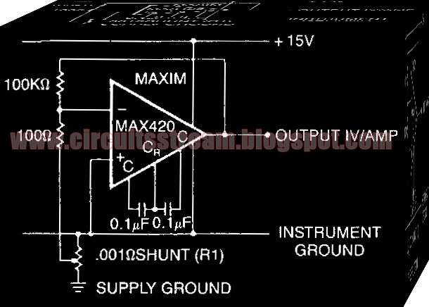
This is a Simple Current Shunt Amplifier Circuit Diagram. Current sense amplifiers (also called current shunt amplifiers) are special-purpose amplifiers that output a voltage proportional to the current flowing in a power rail. 

 Simple Current Shunt Amplifier Circuit Diagram


 simple current shunt amplifier circuit diagram


They utilize a "current-sense resistor" to convert the load current in the power rail to a small voltage, which is then amplified by the current-sense amplifiers.This schema measures the power -supply current of a schema without really having a current shunt resistor: R1 is only 3 em of #20 gauge copper wire. 

A length of the power distribution wiring can be used for Rl. The MAX420`s CMVR includes its own negative power supply; therefore, it can both be powered by and measure current in the ground line.
Read More..