Showing posts with label switching. Show all posts
Showing posts with label switching. Show all posts
Monday, November 17, 2014
5 Volt Switching Regulator Power Supply
The switching regulator power supply used LM2575-5.0 on this schematic. You can make the stable voltage by using the 3 terminal regulator like LM317. However, because the output electric current and the inputted electric current are the same approximately, the difference between the input electric power (The input voltage x The input electric current) and the output power (The output voltage x The output current) is consumed as the heat with the regulator. Because it is, the efficiency isn't good. 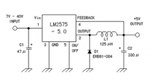
Data sheet for LM2575
SIMPLE SWITCHER 1A Step-Down Voltage Regulator
http://www.national.com/pf/LM/LM2575.htm
Read More..
Data sheet for LM2575
SIMPLE SWITCHER 1A Step-Down Voltage Regulator
http://www.national.com/pf/LM/LM2575.htm

Monday, November 3, 2014
CHALLENGES DESIGN OF SWITCHING LED ELECTRONIC DIAGRAM

CHALLENGES DESIGN OF SWITCHING LED ELECTRONIC DIAGRAM
The LED WEBENCH® online design environment predicts and simulates the response of an LED to constant current while taking into account several potential design parameters that are new to designers of traditional switching regulators.
Monday, September 15, 2014
Low power switching regulator
This circuit is a simple battery-powered switching regulator provides 5V out from a 9V source with 80% efficiency and 50-mA output capability. When Q1 is oon , its collector voltage rises , forcing current trhough the iinductor. The output voltage rises , causing A1s output to rise . Q1 cutts off and the output drops low enough for A1 to turn Q1. The 1 uF capacitor ensures low battery impedance at high frequencies , preventing sag during switching. See schematic diagram below :

Saturday, September 13, 2014
12 Volt 2 A Switching Power Supply Wiring diagram Schematic
This is a Simple 12 Volt / 2 A Switching Power Supply Circuit Diagram. The schema 12 volt / 2 A switching power supply in the above scheme is not too complicated. At the output of this block provides a stable 12 V and maximum current 2A. Power supply units are quite compact and is suitable for debugging schemes, as well as a permanent resource for stationary devices, including power for the logic electronics for the home-made CNC machine tools.
12 Volt / 2 A Switching Power Supply Circuit Diagram
Transformer is available in the free market and avoids the hassle of having to self-winding. The diode bridge BR 1 of any given voltage and current of 2A. All other elements in the high part of the schema are designed by the same voltage, taking into account the mains. The scheme of 12 volt / 2 A switching power supply operates from the high voltage network, to be observed when mounting accuracy and caution when using. It is desirable to block the finished board to “pack” in the body.
Sourced By : Circuitsstream
Friday, September 12, 2014
LM1758 A Switching Regulator Circuit
The National Semiconductor LM 1578 A is very a switching regulator Which should easily be set up for such dc-to-dc voltage .conversion circuits as the buck, boost, and inverting configurations. The LM 1578 A features a distinctive comparator input stage Which not just} has separate pins for both the inverting and non-inverting inputs, but as well offers an internal 1.0 V reference to every input, thereby simplifying circuit design and PC board layout.
The output can switch upto 750 m A and has output pins for its collector and emitter to market design flexibility. An external current limit terminal tend to be referenced to either the ground or the Vin terminal, depending upon the application. In addition, the LM 1578 A has an on board oscillator, Which sets the switching frequency with other a single external capacitor in one < 1 Hz to 100 kHz (typical). It operates in one supply voltages of 2 V to 40 V. its really provided with other current limit and thermal shutdown. Duty cycle up to 90 %. Functional diagram is given in figure.
Sunday, September 7, 2014
Adjustable switching power supply
Switching Regulator L4970 series include not complicated to make his own, which need to be considered is the IC L4970 require sufficient cooling to operate in an optimal and durable. Adjustable Switching Regulator L4970 series are complete can be seen in thethe following figure .
| Adjustable switching power supply schematics |
To set the output voltage range Adjustable Switching Regulator L4970 can be in control by adjusting the potentiometer 18KOhm tus.
Monday, September 1, 2014
Switching Mode Power Supply using STR
| Switching power supply |
This power supply circuit is a type SMPS (Switching Mode Power Supply) using mosfet transistor integrated circuit voltage controller in one IC package, namely STR-W6654. This IC will control the duty cycle of time off Vth2 Mosfet transistor to control the output voltage. Besides, the IC is also equipped with a safety circuit against overvoltage (OVP), overcurrent (OCP) and over temperature (TSD) circuit is working on 220V ac voltage with the input ac voltage range of 176V to 260V ac or known by the Wide range Regulators.
How to Work Series
Initial bias voltage dc pin6 IC801 obtained from an ac voltage through D811 and R817, in the beginning of this pin6 high input impedance, or simply need a current of about 100uA, if the voltage has reached the 10V, the IC will mendrive Mosfet transistor into On and transformer will generate stress induction through V1 , R819 and D816 making this pin6 voltage rises to 16V working voltage, and at this point impedance pin6 will shrink or current will increase to 30mA.
Voltage Stabilizer
Stabilizing the output voltage of the circuit is done by regulating the length of time off of the transistor current MOSFETs by using the feedback coupler photo released by the D807. And the D807 is controlled by the IC regulator IC802, IC is working based on the transformer secondary winding S2 (main output). Change IC802 PIN1 perceived stress will be informed on the photo coupler D807 and forwarded to the IC801 for correction.
Safety Over Voltage
In the event of errors / defects in the feedback path, the output voltage will rise out of control, but the series / IC801 has been equipped with a safety overvoltage, where pin6 IC801 can serve as a detection voltage, output voltage rises when the voltage V1 uncontrolled transformer also rises and via the R819, D816 IC801 pin voltage also rose, When the voltage reaches 34V in IC801 oscillator will stop / off switch and voltage pin6 will go down, and when the voltage reaches 7.5 V IC is going back to work and pin6 voltage rises again, if it again reaches 34V IC will die, so planes demikiian will be dead-alive, dead-alive.
Safety Flow / Cost More
The series is able to secure the power supply circuit to the flow or more load by detecting current flowing in the drain-source transistors MOSFETs. By placing a resistor R809, R835, and R811 on pin3 (source) and connected to pin7 (OCP), the more current or voltage drop on this resistor can be directly detected by a safety circuit overcurrent (OCP). In the event of overload or over current IC will stop for pin 6 voltage above 7.5V
Safety Over Temperature
IC STR-W6654 is also equipped with over temperature safety circuit (TSD). If an error occurs in the IC cooling load or metal, can cause uncontrolled temperature rise IC if IC exceeds 140 degrees then it will stop. The aircraft can live again when the voltage is below 7.5V pin6 (main switch is turned off) and the temperature has dropped below 140 degrees.
Stand-By Condition
With working characteristics pin6 tapped IC STR-W6654 especially voltage Latch Circuit Release Voltage (7.5V) the IC can be made to work on a very small load conditions (stand-by)
How it works series Stand-By
In normal conditions PIN1 UOC IC output is 5V (high) and on stand-by condition 0V (low). If the output of PIN1 UOC Low, Q852 off, Q857 is on, thus the input voltage to 10V PIN2 of IC 802 that will cause the output voltage to 52 volts IC801 PIN1. Thats due to the influence of input voltage PIN1 decreased from 26 V to 10V. so that the circuit feed back will inform you as there is more current. IC 801 IC801 stop temporarily until voltage falls below 7.5V pin6. After reaching 7.5V IC801 automatically revived. So this event will be repeated with certain intervals. The fall in line with all automatic 90V secondary circuit also fell, including PIN1 (V1) transformer. If the transformer voltage drop V1 also fell tentunnya pin6 IC801, IC801 will follow the working characteristics pin6.
In the event of errors / defects in the feedback path, the output voltage will rise out of control, but the series / IC801 has been equipped with a safety overvoltage, where pin6 IC801 can serve as a detection voltage, output voltage rises when the voltage V1 uncontrolled transformer also rises and via the R819, D816 IC801 pin voltage also rose, When the voltage reaches 34V in IC801 oscillator will stop / off switch and voltage pin6 will go down, and when the voltage reaches 7.5 V IC is going back to work and pin6 voltage rises again, if it again reaches 34V IC will die, so planes demikiian will be dead-alive, dead-alive.
Safety Flow / Cost More
The series is able to secure the power supply circuit to the flow or more load by detecting current flowing in the drain-source transistors MOSFETs. By placing a resistor R809, R835, and R811 on pin3 (source) and connected to pin7 (OCP), the more current or voltage drop on this resistor can be directly detected by a safety circuit overcurrent (OCP). In the event of overload or over current IC will stop for pin 6 voltage above 7.5V
Safety Over Temperature
IC STR-W6654 is also equipped with over temperature safety circuit (TSD). If an error occurs in the IC cooling load or metal, can cause uncontrolled temperature rise IC if IC exceeds 140 degrees then it will stop. The aircraft can live again when the voltage is below 7.5V pin6 (main switch is turned off) and the temperature has dropped below 140 degrees.
Stand-By Condition
With working characteristics pin6 tapped IC STR-W6654 especially voltage Latch Circuit Release Voltage (7.5V) the IC can be made to work on a very small load conditions (stand-by)
How it works series Stand-By
In normal conditions PIN1 UOC IC output is 5V (high) and on stand-by condition 0V (low). If the output of PIN1 UOC Low, Q852 off, Q857 is on, thus the input voltage to 10V PIN2 of IC 802 that will cause the output voltage to 52 volts IC801 PIN1. Thats due to the influence of input voltage PIN1 decreased from 26 V to 10V. so that the circuit feed back will inform you as there is more current. IC 801 IC801 stop temporarily until voltage falls below 7.5V pin6. After reaching 7.5V IC801 automatically revived. So this event will be repeated with certain intervals. The fall in line with all automatic 90V secondary circuit also fell, including PIN1 (V1) transformer. If the transformer voltage drop V1 also fell tentunnya pin6 IC801, IC801 will follow the working characteristics pin6.
Subscribe to:
Posts (Atom)
