Showing posts with label regulator. Show all posts
Showing posts with label regulator. Show all posts
Monday, November 17, 2014
5 Volt Switching Regulator Power Supply
The switching regulator power supply used LM2575-5.0 on this schematic. You can make the stable voltage by using the 3 terminal regulator like LM317. However, because the output electric current and the inputted electric current are the same approximately, the difference between the input electric power (The input voltage x The input electric current) and the output power (The output voltage x The output current) is consumed as the heat with the regulator. Because it is, the efficiency isn't good. 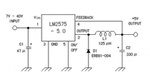
Data sheet for LM2575
SIMPLE SWITCHER 1A Step-Down Voltage Regulator
http://www.national.com/pf/LM/LM2575.htm
Read More..
Data sheet for LM2575
SIMPLE SWITCHER 1A Step-Down Voltage Regulator
http://www.national.com/pf/LM/LM2575.htm
Monday, October 27, 2014
Very Simple Pre Regulator
Present desire be there many period anywhere it is considered necessary to waste the P05 supply module from a upper voltage source. intended for case, if you lack to add balanced inputs to a power amplifier, next you need a +/-15V supply, but the amps supply voltage willpower survive much too far above the ground for the manager ICs.
This project is roughly speaking to the same extent unpretentious as they take place, and is very economical to build. It is designed in support of exactly this reason - to reduce the amplifier supply voltage to a safe significance for controller ICs.
The circuit it is very down-to-earth indeed. You desire need to make it to a hardly any simple calculations to determine the resistor value, but this is explained beneath.

The circuit made known uses the 24V zener diodes (D1 and D2) to adjust the output voltage to a unimportant under 24V. This is a seamlessly safe input voltage in favor of standard 3-terminal regulators, and using this circuit long for provide even better guideline and supply clamor rejection at that time typical. Using MJE3055 and 2955 transistors will allow for supply voltages up to 70V quite safely, but they will need to take place mounted on a heatsink (with insulating washers).
The single-mindedness of R5 is to detach the foremost power amplifier ground from the supply, to prevent hum loops. The 10Ω resistor revealed motivation be fine in lieu of the vast majority of applications, but might need to remain untouched. This is up to you to research with if essential. I hint at so as to R5 ought to be 1W. R2 and R4 may perhaps be 1/4W before 1/2W resistors, and 1W zeners are recommended.
The lone calculation is to determine the regard in support of R1 and R3. original, quantify the power amp supply voltage (V1). The resistor value is calculated to provide a top figure zener current of 20mA, and this hope against hope ensure sufficient found current for the pass transistors representing up to 100mA before so output current by the side of ±15V.
V2 = V1 - 24 (someplace V1 is amplifier supply voltage, and a 24V zener is used)
R1 = R3 = V2 / 20 (R1 and R3 morals are arrived kΩ)
P = V2² / R1 (P is power dissipation of R1 and R3 in mW)
consent tos begin to have a supply voltage of ±56V meant for an pattern calculation ...
V2 = 56 - 24 = 32V
R1 = R3 = 32 / 20 = 1.6k (practice 1.5k)
P = 32² / 1.5 = 680mW = 0.68W (use 1W)
The dissipation in Q1 and Q2 could as well be located calculated, but you need to know the current drawn by the outdoor circuits. on behalf of instance, if the external circuitry draws 50mA, the transistor power dissipation is ...
Pt = V2 * Iext = 32 * 50 = 1600mW = 1.6W (it self-control need a slight heatsink)
Sunday, October 5, 2014
2N3055 using ic 5 Volt Linear power supply regulator

This is 5 Volt Linear power supply regulator circuit. It uses electronics part that seek easily have no zener diode , and the integrated circuit use Transistor 2N3055 and other. Which seek easily use diode perform heal voltage be stable. By diode 1N914 number uses 1N4148 number can replace. For Transistor 2N3417 use the number BD139 equiv get. If use Transformer 1-2A circuit be this size give current get about 1 Amp. Friends may don’t be bored with line this circuit. I thinks it may advantage seek part easy and economize good yes.
Monday, September 15, 2014
Low power switching regulator
This circuit is a simple battery-powered switching regulator provides 5V out from a 9V source with 80% efficiency and 50-mA output capability. When Q1 is oon , its collector voltage rises , forcing current trhough the iinductor. The output voltage rises , causing A1s output to rise . Q1 cutts off and the output drops low enough for A1 to turn Q1. The 1 uF capacitor ensures low battery impedance at high frequencies , preventing sag during switching. See schematic diagram below :

Friday, September 12, 2014
LM1758 A Switching Regulator Circuit
The National Semiconductor LM 1578 A is very a switching regulator Which should easily be set up for such dc-to-dc voltage .conversion circuits as the buck, boost, and inverting configurations. The LM 1578 A features a distinctive comparator input stage Which not just} has separate pins for both the inverting and non-inverting inputs, but as well offers an internal 1.0 V reference to every input, thereby simplifying circuit design and PC board layout.
The output can switch upto 750 m A and has output pins for its collector and emitter to market design flexibility. An external current limit terminal tend to be referenced to either the ground or the Vin terminal, depending upon the application. In addition, the LM 1578 A has an on board oscillator, Which sets the switching frequency with other a single external capacitor in one < 1 Hz to 100 kHz (typical). It operates in one supply voltages of 2 V to 40 V. its really provided with other current limit and thermal shutdown. Duty cycle up to 90 %. Functional diagram is given in figure.
Sunday, August 10, 2014
Build a Simple 90Vrms Voltage Regulator Circuits Wiring diagram
This is a Simple 90Vrms Voltage Regulator Circuits Diagram. The 90Vrms Voltage Regulator Circuits Diagram is an open loop rms voltage regulator that will provide 500 watts of power at 90 V rms with good regulation for an input voltage range of 110-130 V rms. With the input voltage applied, capacitor Cl charges until the firing point of Q3 is reached causing it to fire.
This turns Q5 on which allows current to flow through the load. As the input voltage increases, the voltage across R10 increases which increases the firing point of Q3. This delays the firing of Q3 because Cl now has to charge to a higher voltage before the peak-point voltage is reached.Thus the output voltage is held fairly constant by delaying the firing of Q5 as the input voltage increases. For a decrease in the input voltage, the reverse occurs.
90Vrms Voltage Regulator Circuits Diagram

Subscribe to:
Posts (Atom)
