Showing posts with label 5. Show all posts
Showing posts with label 5. Show all posts
Monday, November 17, 2014
5 Volt Switching Regulator Power Supply
The switching regulator power supply used LM2575-5.0 on this schematic. You can make the stable voltage by using the 3 terminal regulator like LM317. However, because the output electric current and the inputted electric current are the same approximately, the difference between the input electric power (The input voltage x The input electric current) and the output power (The output voltage x The output current) is consumed as the heat with the regulator. Because it is, the efficiency isn't good. 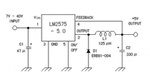
Data sheet for LM2575
SIMPLE SWITCHER 1A Step-Down Voltage Regulator
http://www.national.com/pf/LM/LM2575.htm
Read More..
Data sheet for LM2575
SIMPLE SWITCHER 1A Step-Down Voltage Regulator
http://www.national.com/pf/LM/LM2575.htm

Sunday, October 5, 2014
2N3055 using ic 5 Volt Linear power supply regulator

This is 5 Volt Linear power supply regulator circuit. It uses electronics part that seek easily have no zener diode , and the integrated circuit use Transistor 2N3055 and other. Which seek easily use diode perform heal voltage be stable. By diode 1N914 number uses 1N4148 number can replace. For Transistor 2N3417 use the number BD139 equiv get. If use Transformer 1-2A circuit be this size give current get about 1 Amp. Friends may don’t be bored with line this circuit. I thinks it may advantage seek part easy and economize good yes.
Thursday, September 18, 2014
Wednesday, August 20, 2014
Build a Variable 5 to 20V DC Supply Wiring diagram Schematic
This is a Variable 5 to 20V DC Supply Circuit Diagram. If you are looking for a low drop voltage regulator that can provide a power supply of 1A with an output voltage of between 5V and 20V DC, National Semiconductor LM2941 Low Dropout Adjustable Regulator is that you can pick to make use of. Its a typical dropout voltage of 0.5V which means that the input supply need only must be 0.5V DC over the desired output voltage.
Variable 5 to 20V DC Supply Circuit Diagram
Its other features include internal short schema current limit and reverse battery protection. As shown in the schematic below, the regulator has five pins which consists of the ON/OFF control, Input Voltage, Output Voltage, Ground & Adjustable pins. ON/OFF is used for the purpose of switching on & off of the regulator. The capacitors C1 & E1 are to be placed as close as feasible to the regulator.
The output of the schema can be varied by varying the worth of potentiometer VR1 from 5V DC to 20V DC. The input voltage is limited from five.5V DC to 30V DC. Resistor R1 must be greater than 1K. The worth of the VR1 that needs to be set is calculated from the formula given below:
VR1 = R1[(Vout/1.275) - 1] ohm
If R1=1K, Vout = 5V, VR1 should be set to 2.9K ohm.
If R1=1K, Vout = 20V, VR1 should be set to 14.7K ohm

Subscribe to:
Posts (Atom)
