Showing posts with label inverter. Show all posts
Showing posts with label inverter. Show all posts
Monday, November 17, 2014
Simple 100W inverter circuit
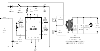
Here is the circuit diagram of a simple 100 watt inverter using IC CD4047 and MOSFET IRF540. The circuit is simple low cost and can be even assembled on a veroboard.

CD 4047 is a low power CMOS astable/monostable multivibrator IC. Here it is wired as an astable multivibrator producing two pulse trains of 0.01s which are 180 degree out of phase at the pins 10 and 11 of the IC. Pin 10 is connected to the gate of Q1 and pin 11 is connected to the gate of Q2. Resistors R3 and R4 prevents the loading of the IC by the respective MOSFETs. When pin 10 is high Q1 conducts and current flows through the upper half of the transformer primary which accounts for the positive half of the output AC voltage. When pin 11 is high Q2 conducts and current flows through the lower half of the transformer primary in opposite direction and it accounts for the negative half of the output AC voltage.
Circuit diagram.
Notes.
B1 can be a 12V/ 6Ah lead acid battery.
Q1 and Q2 must be fitted to a proper heat sink.
T1 can be a 9-0-9 V primary, 230V secondary, 150VA transformer .
Do not expect much from this circuit. The is very simple one suitable for low grade applications.

Wednesday, November 12, 2014
Simple 12V DC to 220V 100W Inverter
This is 100W inverter circuit. It uses 4047 IC and IRF540 Mosfet instead of 2N3055 transistor. Power output is 100W from 2-3A transformer.
Tuesday, October 14, 2014
MOSFET IRF540 based 100W 12VDC to 220VAC Inverter diagram
The following inverter circuit is using MOSFET transistor IRF540 instead of ordinary transistor (eq 2N3055). FET is better than ordinary transistor in both stability and responsibility.
Sunday, October 5, 2014
110VAC Car Inverter Circuit
110VAC Car Inverter Circuit
This circuit will allow you to operate small devices like laptop computers inside your automobile without an expensive automobile power supply. The circuit takes advantage of the fact that power transformers are linear devices and can be used to step up as well as step down. This is evident by the fact that the supply drives the secondary and the output is on the primary.
Warning: this supply produces dangerous and lethal voltages. Use extreme caution when testing this circuit. In addition, make sure the assembly is enclosed in a plastic case. Do not package this circuit in a metal or aluminum case!
The design depends on the windings ratio and the value of the car battery to produce an AC waveform of approximately 95 volts RMS. No filtering is performed on the secondary since the transformer blocks most of the sharp edges from the input waveform.
All of the devices (14013, 555, 14020, and 4049) should have their supply pins connected to the +12 supply. The nice thing about CMOS logic is that it will operate over a wide range of voltages. Before connecting the center tap of the transformer, adjust R3 until the signal on U5 pin 13 is 120Hz.
The 14013s are used to produce a 60Hz square wave with an accurate 50% duty cycle and to force the FET switches operate in a break-before-mate manner. The 4049s have enough drive capability to snap the FETs off and on very quickly.
Warning: this supply produces dangerous and lethal voltages. Use extreme caution when testing this circuit. In addition, make sure the assembly is enclosed in a plastic case. Do not package this circuit in a metal or aluminum case!
The design depends on the windings ratio and the value of the car battery to produce an AC waveform of approximately 95 volts RMS. No filtering is performed on the secondary since the transformer blocks most of the sharp edges from the input waveform.
All of the devices (14013, 555, 14020, and 4049) should have their supply pins connected to the +12 supply. The nice thing about CMOS logic is that it will operate over a wide range of voltages. Before connecting the center tap of the transformer, adjust R3 until the signal on U5 pin 13 is 120Hz.
The 14013s are used to produce a 60Hz square wave with an accurate 50% duty cycle and to force the FET switches operate in a break-before-mate manner. The 4049s have enough drive capability to snap the FETs off and on very quickly.
Wednesday, August 27, 2014
6 to 12 Volt Power Supply Inverter
This inverter circuit can provide up to 800mA of 12V power from a 6V supply. For example, you could run 12V car accessories in a 6V (British?) car. The circuit is simple, about 75% efficient and quite useful. By changing just a few components, you can also modify it for different voltages.
![6]()
Part List:
R1, R4 2.2K 1/4W Resistor
R2, R3 4.7K 1/4W Resistor
R5 1K 1/4W Resistor
R6 1.5K 1/4W Resistor
R7 33K 1/4W Resistor
R8 10K 1/4W Resistor
C1,C2 0.1uF Ceramic Disc Capacitor
C3 470uF 25V Electrolytic Capcitor
D1 1N914 Diode
D2 1N4004 Diode
D3 12V 400mW Zener Diode
Q1, Q2, Q4 BC547 NPN Transistor
Q3 BD679 NPN Transistor
L1 See Notes
MISC Heatsink For Q3, Binding Posts (For Input/Output), Wire, Board
Read More..
Part List:
R1, R4 2.2K 1/4W Resistor
R2, R3 4.7K 1/4W Resistor
R5 1K 1/4W Resistor
R6 1.5K 1/4W Resistor
R7 33K 1/4W Resistor
R8 10K 1/4W Resistor
C1,C2 0.1uF Ceramic Disc Capacitor
C3 470uF 25V Electrolytic Capcitor
D1 1N914 Diode
D2 1N4004 Diode
D3 12V 400mW Zener Diode
Q1, Q2, Q4 BC547 NPN Transistor
Q3 BD679 NPN Transistor
L1 See Notes
MISC Heatsink For Q3, Binding Posts (For Input/Output), Wire, Board
source:LINK
Thursday, August 14, 2014
Build a High voltage Inverter Wiring diagram Schematic
This is a simple High voltage inverter schema diagram. This inverter schema works with a transistor and transformer and other components to increase the voltage becomes high. Input supply voltage ranging from 3V to 6V DC, later it was raised to high voltage AC. However, in this inverter schema output current is very small, probably under 0.1A even smaller. However, its use you can apply it on a fluorescent lamp 10W maximum power only, and that too takes time to switch on fluorescent lamps.
High voltage inverter schema diagram

Part List
R1 = 4K7
R2 = 2K2
R3 = 330K
C1 = 100nF
C2 = 100nF 275V
C3 = 0.22uF 275V
Q1 = D506
L1 = 100 times winding, with 0.8mm diameter copper wire
L2 = 50 times winding, with 0.8mm diameter copper wire
L3 = 5000 times winding, with 0.4mm diameter copper wire
Subscribe to:
Posts (Atom)
