Wednesday, November 19, 2014

Measure your stress level – Tension meter

If you, like so many other people in this day and age, arrive home from work stressed out and with the problems of the day still lingering,this simple little instrument will go a long way to relieving nervous tension.
Of the various types of feedback devices, probably the best approach for the amateur experimenter is the Galvanograph, better known as the Galvanic Skin Response Monitor. The instrument described here relies for its operation on changes in skin resistance in sympathy with changes in emotional state. An increase in tension level reduces skin resistance and, conversely, a decrease in tension is accompanied by an increase in skin resistance.
The correlation between emotional stress and skin resistance is still not fully understood. What is known, though, is that minute changes in the permeability of the skin produce corresponding voltage variations across two electrode pads attached to two fingers on the same hand.
Measure


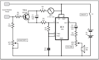
Tension Monitor meter circuit

These signal fluctuations are amplified and fed to an oscillator to produce an audible tone. A decrease in pitch therefore signifies a decrease in tension, and vice-versa. A visual indicator in the form of a panel meter also aids the user in monitoring tension levels. The monitor is quite sensitive to fluctuations. During use, a sudden moment of stress, even a deep sigh, will increase the pitch and cause a shift of the meter needle. Circuit Details In the circuit diagram of Fig.1, IC1 is configured as an astable multivibrator to drive an 8-ohm miniature speaker LS1 via capacitor C3, resistor R6 and volume control potentiometer VR2. The latter allows users to set a desired level and avoid it becoming a distraction.
Whereas the trigger input of IC1 is normally connected to the positive rail via a resistor in a conventional 555 oscillator, here it is connected via resistor R4 to the emitter of transistor TR1. The base of TR1 is connected between one electrode pad and the voltage divider formed by potentiometer VR1 and resistor R1. It will be seen that with the pads fitted to the fingers, the tone level will be dependent on the setting of VR1 and skin resistance. Resistor R2 in the transistor base is necessary should the pads be accidentally touched together. A 1mA meter is fitted in the collector line, along with R3, as a visual indicator. Although not essential or intended to measure current levels, it does help to emphasize fluctuations in emotional level.
The design of the pads is not critical. For the prototype, stripboard was used. The tracks were wired together at one end and connected to a 30cm length of twin lighting flex. The pads were then glued to Velcro straps. When the unit is first switched on, a highpitched tone should be heard, rapidly diminishing and ceasing. Turn the Sensitivity control VR1 to the minimum setting. Attach the electrodes to the fleshy pads of the first two fingers on the less-dominant hand with the Velcro straps, firmly but not tight. Rest the hand comfortably and keep it reasonably still, allowing half a minute for the pads to “bond”. Normally, at the minimum setting, the oscillator will hardly tick over, unless the user is in a high state of anxiety. Keep in mind that any form of stimulant, and that includes tea, coffee, alcohol and cigarettes, will reduce one’s capacity to relax. Rotate the control until a medium pitched tone is obtained and apply your relaxation technique. The monitor does not teach any method of meditation or relaxation; it only monitors the effectiveness of the technique applied. The tone should slowly diminish, with fluctuations as unconscious thoughts flit across the mind.When the sound ceases altogether, repeat the above procedure by increasing VR1. Twenty minutes is considered by therapists to be an adequate relaxation session.
Read More..

Tuesday, November 18, 2014

FM Receiver TV Tuner TDA7000

FM Receiver / TV Tuner TDA7000

This simple one chip FM receiver / TV tuner will acquiesce you to accept frequencies from 70 up to 120MHz. With this baby receiver it is accessible to auto TV stations, absolute 88 - 108MHz FM band, aircraft chat and abounding added clandestine transmissions. It is a absolute accompaniment to any FM Transmitter abnormally if FM bandage in your breadth is actual crowded. TDA7000 receiver offers actual acceptable acuteness accordingly it will alike acquiesce you to auto weaker signals that cannot be heard on accepted FM receivers.

A accurate affection of presented TDA7000 FM receiver is a voltage controlled oscillator agnate to TV tuners that are acclimated in television sets. Abundance is acquainted by capricious the ascribe voltage to the oscillator. The advantage of this blazon of oscillator is that you can use approved 100K potentiometer to absolutely tune to a accustomed broadcast. Tuning can be performed abundant quicker and absolutely than by application a trimmer (variable capacitor). Trimmers will additionally about-face the abundance as you blow them area potentiometer will not. Trimmer additionally needs to be placed on receivers PCB to abbreviate the devious capacitance area potentiometer can be calmly placed anywhere you appetite because it will not be afflicted by any alien capacitance.

Read More..

10A High Current variable power supply

Power supply has 10A maximum current and output voltage can be set from 2 - 36VDC. Power supply circuit is quite simple, which is composed of the rectifier, voltage regulator and power regulator. Power regulator circuit High Current Variable Power Supply 10A uses the Q3 and Q4 are arranged Darlington and serves as a power regulator drivers Q5 and Q6. While the voltage regulator circuit is VR1 which serves as a variable voltage divider and Q1 and Q2 are arranged as a controller driver Darlington power regulator with variable reference voltage divider VR1.
10A

In a series of High Current Variable Power Supply 10A 10A above have been completed as a current-limiting fuse. and to monitor the current flowing with ampere meter and volt meter to monitor the output voltage of the circuit.
Read More..

Altium Designer 10 0 – Free Download

A unified electronic product development solution Altium Designer is the world’s first and only unified electronic product development system that allows engineers to take a design from concept to completion within a single application.

Don’t limit your design horizons. Get yourself out of the traditional design box and into holistic design. Use all the available technologies and devices to bring your ideas to life and turn them into the smart, connected products that we’ll all be using tomorrow.

Altium

Altium Designer 10.0

That’s what Altium Designer is all about – freeing you from the constraints of traditional design limitations and the old “divide and conquer” approach. Altium Designer provides one single unified solution for the entire design process. It allows you to explore and do more, do it in new ways, and design things that haven’t even been thought of yet. Think and design beyond the confines of the device itself and start designing your customer’s total product experience.

That’s next-generation electronics design. That’s Altium Designer.

The entire product development process with a single unified design solution A single solution to develop hardware, programmable hardware and software Take designs from concept to manufacture within a single unified environment A single model of the design data, and a single design data storage system

Freely explore design concepts ‘on-the-fly’ Explore devices from different vendors with minimal design reengineering Easily explore design concepts and options before committing to final hardware Use IP from any source, without being restricted to vendor-specific ‘sticky IP’

Rapidly prototype using a live, interactive hardware development system Develop, explore and debug designs on real hardware, in real-time with ‘LiveDesign’ Harness the full potential of reprogrammable devices with soft-centric design Change software and hardware with equal ease and on-the-fly

Smooth the path from design to board layout and manufacture Single centralized data source simplifies version control and component management Visualize and interact with board designs in real-time 3D, within the PCB editor Seamless collaboration with MCAD designers and other engineering teams

Easily connect to wider company systems Single access point for all design data simplifies links for data management systems Plug-in capability and built-in interfaces for external data management All involved in product development process access one design environment

Be equipped for the future with the latest design technologies Expand existing skill sets while harnessing the latest devices and techniques Make soft design and the creation of device intelligence the focus of design Immediately access new technology through consistent and frequent updates

Be productive right ‘out-of-the-box’ All tools and technologies in the box, including parts libraries and royalty-fee IP No need to purchase costly add-ons to make a complete solution Continually updated with latest devices and technologies
Read More..

Multiplexer with CMOS IC 4556

In addition to the family of TTL ICs that support the function of a multiplexer is a family of CMOS ICs.

Despite the fact it is the family of TTL ICs that support more functions than the CMOS multiplexer. For the working principle of the multiplexer IC CMOS family is actually tantamount to a multiplexer circuit, or IC TTL logic gates. That should be all referring to the real multiplexer function, namely the determination of output lines which represent the number of input lines. The use of symbols is possible between TTL and CMOS IC has a different but actually run the same rules. For your reference if you are interested in using family of CMOS IC 4556 series in particular, I include also the truth table below:


INPUT
OUTPUT
E
A0
A1
O0
O1
O2
O3
L
L
L
L
H
H
H
L
H
L
H
L
H
H
L
L
H
H
H
L
H
L
H
H
H
H
H
L
H
X
X
H
H
H
H
L = LOW
H = HIGH
Read More..

Monday, November 17, 2014

5 Volt Switching Regulator Power Supply
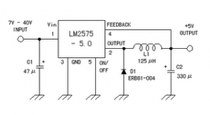
The switching regulator power supply used LM2575-5.0 on this schematic. You can make the stable voltage by using the 3 terminal regulator like LM317. However, because the output electric current and the inputted electric current are the same approximately, the difference between the input electric power (The input voltage x The input electric current) and the output power (The output voltage x The output current) is consumed as the heat with the regulator. Because it is, the efficiency isn't good. 5

Data sheet for LM2575
SIMPLE SWITCHER 1A Step-Down Voltage Regulator
http://www.national.com/pf/LM/LM2575.htm
Read More..

Electric Motor Repair

Electrical engines are a significant aspect of most large functions. They are used to make current that can be linked with a strength or to immediately petrol other systems. These engines are complicated items of professional systems and consequently it is not recommended for a individual who is not a certified fix individual to attempt to fix them. This transforms digital strength into technical strength.

They come in a wide range of types and the type that you use will depend on what you need it for. The primary parts are the blades and the stator. The blades is the going aspect and the stator is the invitations aspect of it. These two items make the time frame for it.

Most engines are attractive in characteristics. Both the blades and the stator generate a attractive area which makes a twisting, or demand on the powerplant base and makes the revolving of the powerplant. This is how it functions.

Finding a reliable serviceman for your powerplant can be a complicated procedure. The crucial aspect is making sure that the serviceman you seek the services of is certified in mending. An search can help you discover certified serviceman in your community that can fulfill your immediate and continuing needs.

Once youve found the serviceman or fix company youd like to use, you should have them come and visit the site as soon as possible to analyze it. Once the serviceman has analyzed the position of your powerplant unit, he can give you an calculate regarding the money of the fix.

The fix is the first step in a long procedure of its servicing. Once it has been fixed, youre going to want to set up a frequent servicing routine in order to reduce the cost and agony of upcoming fixes. Maintenance is the single greatest factor you can do to reduce the need for fixes.

The best factor you can do with regards to fix is to put the extra persistence in to make sure that frequent servicing is being done. Effectively managed engines need less fix and cause less problems for you. If you can keep your engines properly managed youre less likely to need comprehensive and expensive fixes.

Electric powerplant fix can take many types, based on what type of powerplant unit you have and the characteristics of its use in your business. The best factor you can do with your damaged powerplant unit is to discover and seek the services of a reliable serviceman to do the fixes. Electrical powerplant fix can be reduced by exercising servicing on your powerplant unit.
Read More..