Saturday, November 15, 2014
60 WATT AMPLIFIER CIRCUIT
Circuit Diagram

Points to Remember
- A good quality PCB improves the performance of the circuit.
- Maximum supply voltage for STK4038 is +/- 57V DC.
- K1 is a 4 ohm / 75 watt loud speaker.
- While using 4 ohm speaker as the load, the power supply must not exceed +/- 32V DC.

Wednesday, November 5, 2014
High Voltage 3 Watt Audio Power Amplifier
 BTL load with less than 1% THD+N from a 7VDC power supply. Boomer audio power amplifiers are designed specifically to provide high quality output power with a minimal number of external components. The LM4954 does not require output coupling capacitors or bootstrap capacitors, and therefore is ideally suited for lower-power portable applications where minimal space and power consumption are primary requirements.
| Wide Power Supply Voltage Range | 2.7 <= VDD <= 9V |
| Output Power: VDD = 7V, 1% THD+N | 2.4W (typ) |
| Quiescent power supply current | 3mA (typ) |
| PSRR: VDD = 5V and 3V at 217Hz | 80dB (typ) |
| Shutdown power supply current | 0.01µA (typ) |
Features:
Friday, October 31, 2014
300 Watt MOSFET Broadband Amplifier Using MRF141G

I recommend getting the two transformer assemblies, instead of trying to create them, due to the fact 15-ohm hardline is not straightforward to come across.
Monday, October 27, 2014
TDA2030 bridge 35 watt power amplifier Diagram Circuit
A very simple 35 watt power amplifier electronic project can be designed using the TDA2030 power audio IC. The TDA2030A is a monolithic IC in Pentawatt package intended for use as low frequency class AB amplifier.
The TDA2030A provides high output current and has very low harmonic and cross-over distortion. TDA2030 ICs connected in bridge mode.
This circuit require few external electronics parts and supports a 8 ohms load . This 35 watt power amplifier require a very good filtered DC power supply , that will provide an output voltage of +/- 16 volts .
Using this circuit you can design a very simple and efficiency subwoofer amplifier with a maximum output power of 35 watt power .
The device incorporates a short circuit protection system comprising an arrangement for automatically limiting the dissipated power so as to keep the working point of the output transistors within their safe operating area. Also a conventional thermal shut-down system is also included .
However a heatsink must be used for the TDA2030 bridge circuit but for any reason, if the junction temperature increases up to 150oC, the thermal shut-down simply reduces the power dissipation and the current consumption.
LM4765 2 x 30 watt amplifier Diagram Circuit
A very simple 2 x 30 watt amplifier electronic circuit project can be designed using the LM4765 stereo audio amplifier IC capable of delivering typically 30W per channel of continuous average output power into an 8Ω load with less than 0.1% THD+N.
This 2 x 30 watt amplifier electronic circuit is very simple and require few external electronic parts and can be used in high end stereo TVs or some other audio applications .
Each amplifier has an independent smooth transition fadein/out mute and a power conserving standby mode which can be controlled by external logic.
Like many other audio amplifier ICs the LM4765 has many features like Temperature protection circuitry, SPiKe protection ( means that these parts are safeguarded at the output against overvoltage, undervoltage, overloads, including thermal runaway and instantaneous temperature peaks).
This audio amplifier electronic circuit project can be powered from a wide input voltage range from 20 volt up to 66 volts , but typically is required a dual 28 volts input ( take care because |Vcc|+|Vee|<60 volts .
The audio IC must be mounted on a heat sink to keep the die temperature at a level such that the thermal protection circuitry does not operate under normal circumstances.
In this circuit diagram is represented just a part of the IC (one channel ) and numbers in parentheses represent pinout for amplifier B
Friday, October 17, 2014
7 Watt Audio Power Amplifier Circuit Schematic
and cross-over distortion. Completely safe operation is guaranteed due to protection against DC and AC short circuit between all pins and ground, thermal over-range, load dump voltage surge up to 40V and fortuitous open ground. A conventional direct current can be connected as supply.
Circuits picture:

Circuit diagram:

Parts:
R1 = 470R
R2 = 47R
R3 = 100R
R4 = 1R
C1 = 1822pF
C2 = 100nF-63V
C3 = 100nF-63v
C4 = 10uF-25V
C5 = 470uF-25V
C6 = 1000uF-35v
C7 = 1000uF-35V
IC1 = TDA2003
Specifications:
- Music power output: 7W / 4ohm
- RMS output: 3.5W / 4ohm or 2W / 8ohm
- Total harmonic distortion: 0.05% (1W / 1kHz)
- Frequency response: 20Hz to 20kHz (-3dB)
- Signal/noise ratio: 86dB (A weighted)
- Input sensitivity: 40mV / 150Kohm
- Overload and short-circuit protected
- Supply voltage: 15V DC (8 to 18V DC possible) / 0.5A
- Dimensions: 2.2 x 1.4"
Wednesday, October 15, 2014
Build a 70 Watt OCL Amplifier Circuit Diagram
70 Watt OCL Amplifier Circuit Diagram

Monday, October 13, 2014
STA575 200 watt stereo power audio amplifier circuit
STA575 power audio amplifier can be set in three states by the Stby/mute pin: Standby ( Vpin <0.8v), mute (1.6v
In the Standby mode all the circuits involved in the signal path are in off condition, instead in Mute mode the circuits are biased but the Speakers Outputs are forced to ground potential.
These voltages can be get by the external RC network connected to Stby/Mute pin.
The same block is used to force quickly the I.C. In standby mode or in mute mode when the I.C. dangerous condition has been detected.
The protection of STA575 power audio amplifier are implemented by the Over Temperature, Unbalance .
The Output bridge amplifier makes the single-ended to Differential conversion of the Audio signal using two power amplifiers, one in non-inverting configuration with gain equal to 2 and the other in inverting configuration with unity gain.
To power this 200 watt stereo power audio amplifier you’ll need a DC power source that will provide the following output voltages : Vs+ = 28V, Vs- = -23V, VCD+ = 20V, VCD- = -20V and you’ll need a 8 ohms load .
In the table bellow you can see values for electronic parts required by this 200 watt stereo power audio amplifier electronic project .
Thursday, September 18, 2014
7 Watt Audio Amplifier Using TDA2003
Schematic diagram of a simple 7 watt audio amplifier using TDA2003 Amplifier IC. This is a good IC with many built in features like low harmonic distortion, short schema protection,thermal overload protection etc. This IC is a upgrade version of TDA 2002 amplifier IC.
7 Watt Audio Amplifier Circuit Diagram :

The schema is small and using only few components and it is able to deliver 7w output on 12V DC. Assamble the schema on PCB or veroboard and use heatsink with IC. Input voltage can be between 8 to 18 volt / 0.5A DC.
Monday, August 25, 2014
60 Watt Subwoofer Amplifer Circuit

OCL 150 Watt with 2N3055 and MJ2955
This is OCL 150 W mono audio amplifier circuit , with impedance 8 Ohms. The supply voltage using 25 volt DC with triple voltage + ,- ,ground. see below this circuit :
Buffer amplifier use PNP transistor is A564 / A733 /A1013 and NPN use D400 / D438. Driver Amplifier use NPN transistor is TIP31 / TIP41 / D401, and PNP transistor use TIP32 / TIP42 / B546. For the transistor booster or end , here I use a 2 x 20355 and MJ2955 . This anplifier is recomended to full range speakers. See pcb line and construction audio amplifier below :
 |
| Click to view larger |
 |
| PCB line |
 |
| Components are already installed |

 |
| The booster amplifier already installed. |
Friday, August 15, 2014
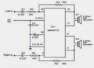
Build a 3 Watt Stereo Amplifier Wiring diagram Schematic
Tuesday, August 12, 2014
22 Watt Stereo Amplifier

